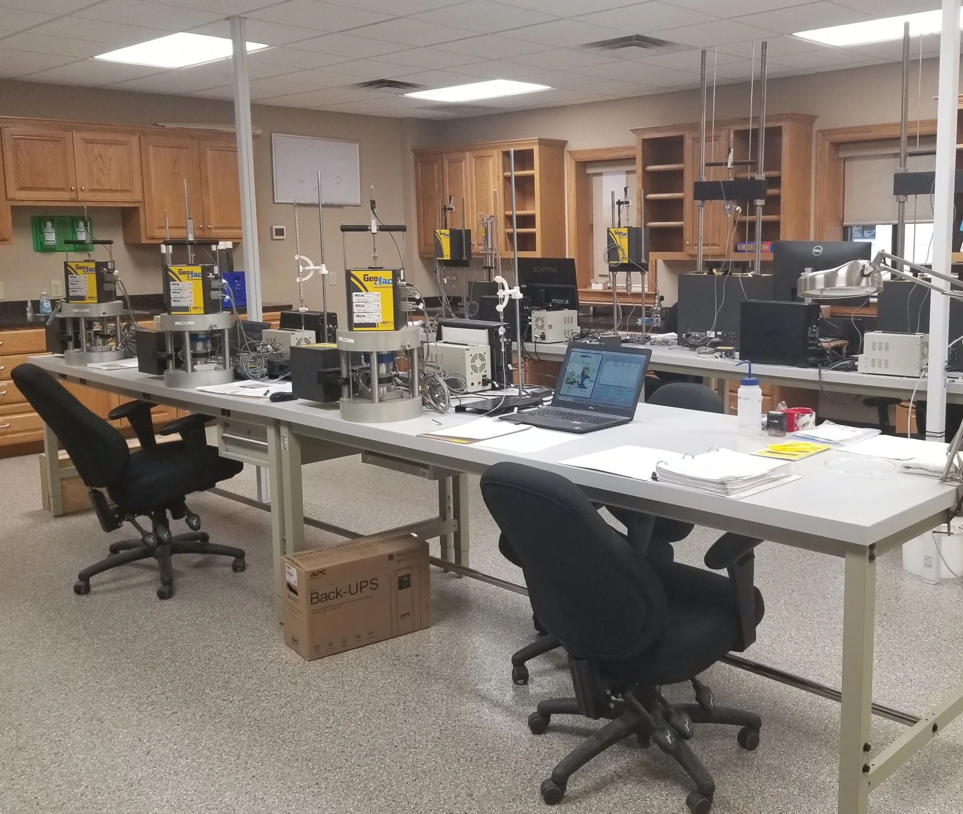
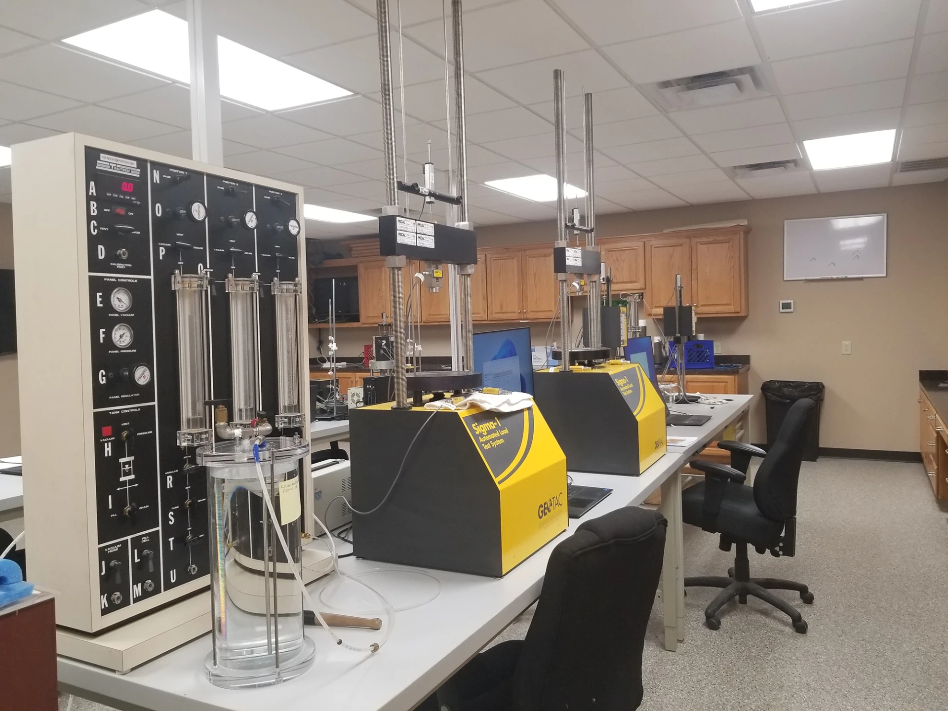
Laboratory testing and data delivery are essential components of any project. With in-house laboratory facilities located worldwide, we provide support wherever your operations take you—onshore or offshore. All of our laboratories are fully accredited and equipped to perform both advanced and routine analyses, ensuring you receive reliable, expert insights precisely when you need them.
Our Geotechnical Laboratory is designed to deliver high-quality, engineering-focused soil testing, logging, and characterization services that support the evaluation of sediment properties critical to the design of major structures.
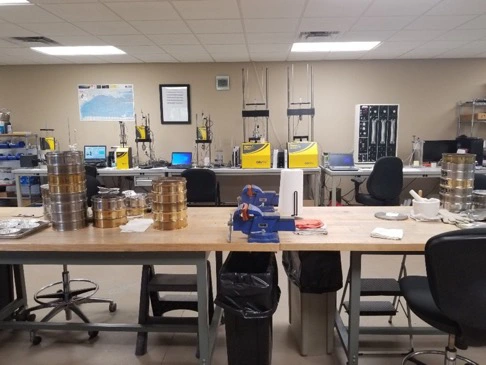
Our laboratory routinely performs the following geotechnical testing:
Atterberg Limits (Plastic Limit, Liquid Limit, and Plasticity Index)
The Atterberg limits are a set of “limits of consistency” of fine-grained soils. In current engineering usage, they are comprised of the plastic limit and the liquid limit. Occasionally, the shrinkage limit is included with the plastic and liquid limits. In most TDI-Brooks projects, the plastic and liquid limits are sufficient for soil characterization. The liquid limit is the water content of a soil at the arbitrarily defined boundary between the semi-liquid and plastic states. The plastic limit is the water content of a soil at the boundary between the plastic and semi-solid states. The plasticity index is the range of water content over which a soil behaves plastically. Numerically, it is the difference between the liquid limit and the plastic limit. Reference ASTM D4318.
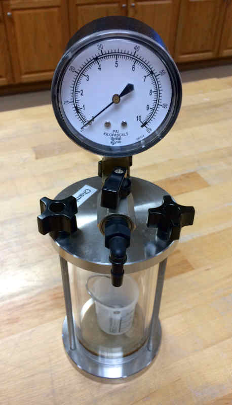
Calcium Carbonate Content
The carbonate content (calcite equivalent) of soil is determined by treating a dried soil specimen with hydrochloric acid in a reactor. Carbon dioxide gas is evolved during the reaction between the acid and carbonate fraction of the specimen. The resulting pressure generated in the closed reactor is proportional to the calcite equivalent of the specimen. This pressure is measured with a suitable pressure gauge that is pre-calibrated with reagent grade calcium carbonate. Reference ASTM D4373.
Core Splitting
Core splitting is our process of cutting a core section down the long axis and separating the two halves. This exposes a vertical cross section of a core, allowing the examination of sediment layers and geologic features. Often, this allows identification of layers for age dating. This is available for fine-grained sediments with high and medium moisture contents. We do not currently offer services for splitting hard/rock samples. Split cores usually receive High Resolution Photography.
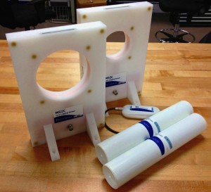
Electrical Resistivity
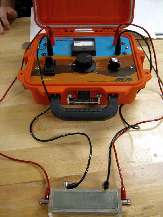
Measurement of sediment electrical resistivity is used for the control of corrosion of buried structures. Electrical resistivity is used both for the estimation of expected corrosion rates and for the design of cathodic protection systems. Resistivity measurements indicate the relative ability of a medium to carry electrical currents. When a metallic structure is immersed in a conductive medium, the ability of the medium to carry current will influence the magnitude of galvanic currents and cathodic protection currents. A soil box with 4 electrodes is used in the lab to conduct this test. Reference ASTM G57.
Grain Size – Hydrometer
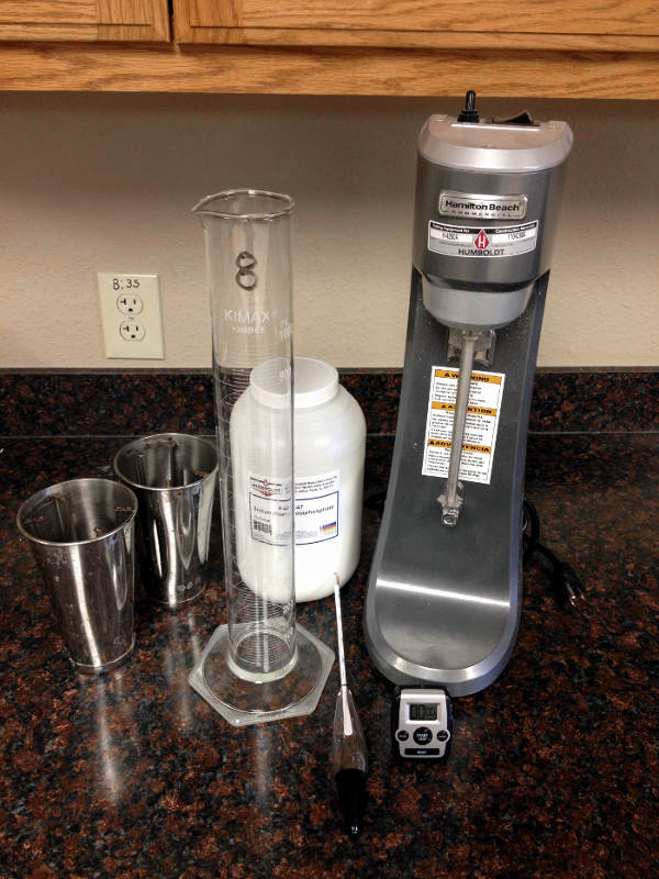
Sediment grain sizes smaller than particles 75 microns can be determined using a sedimentation process. This test is appropriate for marine silts and clays. The particles are initially suspended in solution and then allowed to deposit over time. As they deposit, the density of the solution decreases. The changes in solution density are measured using a hydrometer. The rate at which the particles settle out of suspension can be interpreted to provide grain size distribution, represented by a gradation curve. The gradation curve may also include sieve data generated from the same sample. Reference ASTM D422.
Grain Size – Sieve
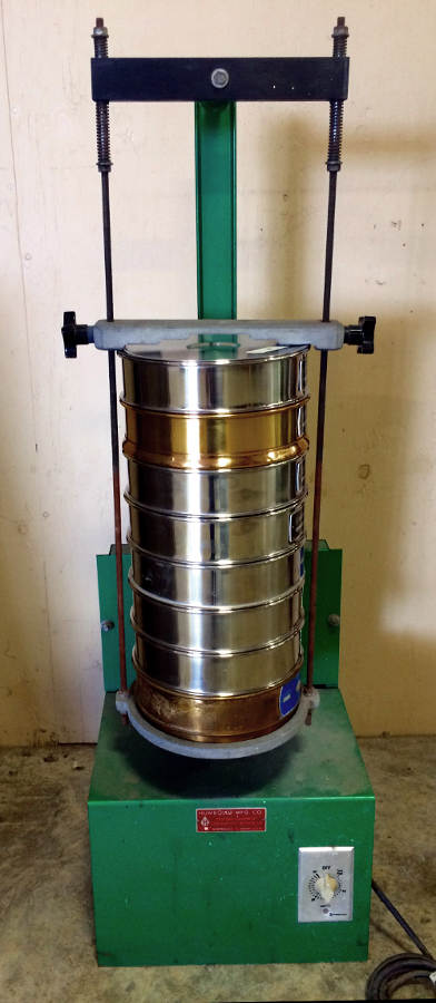
Sediment grain sizes larger than 75 microns can be determined by sieving. A standard sieve set corresponds to specifications in ASTM D422, however, other sieve sizes can be used upon request. The mass of sediment retained on each sieve provides grain size distribution and is plotted on a gradation curve. The gradation curve may also include hydrometer data from the same sample. Reference ASTM D422.
High Resolution Photography
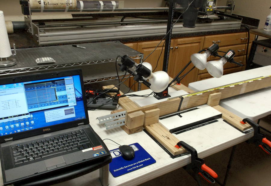
High resolution photography is mostly used in conjunction with Core Splitting. We photograph 10-cm length portions of a core section with a Nikon D90 and merge the photos to generate a single image. These images are typically used by the client for observing geologic characteristics and sedimentology. We can photograph other samples in a high resolution format, but Standard Resolution Photography is also available for documentation and description purposes.
Magnetic Susceptibility
Magnetic susceptibility is a measure of the magnetic behavior of a sediment sample. Magnetic susceptibility measurements provide important information about the composition and properties of materials. In many cases, magnetic susceptibility is done with a multi-sensor core logger. TDI-Brooks can offer this testing separately. Reference Bartington Instruments MS3 Operations Manual.
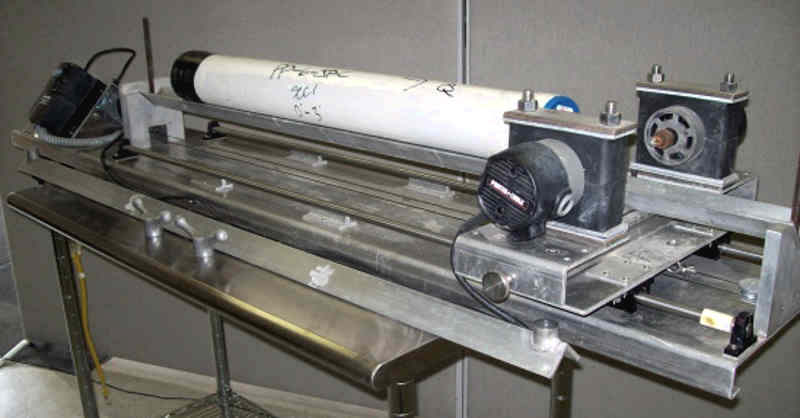
Miniature Vane Shear
Miniature vane shear testing is performed to determine shear strength in very soft to stiff saturated fine-grained clayey sediments. We use a set of 4 calibrated torsion spring sets combined with a motorized vane shear device to determine strength. Reference ASTM D4648.
Moisture Content
Moisture content is a test to determine how much water is in a sediment sample. It is a ratio of the mass of water to the mass of solids, reported in a percent. Since it is a ratio of water to solids, it can, and often does, exceed 100% in marine samples. Reference ASTM D2216.
Multi-Sensor Core Logging (MSCL)
Multi-sensor core logging is a quantitative method to determine geotechnical properties such as bulk density, porosity, void ratios, and water content in sediment cores using a Geotek multi-sensor core logger (MSCL). The MSCL can handle core sections up to 1.5-m long and can sample at intervals of 1-mm or greater and is a non-destructive test.
Percent Sand Determination
Percent sand determination is similar to grain size testing using sieves except that the number of sieves is reduced. A No. 4 sieve is used to separate gravel from the sample. A No. 200 sieve allows all the clay and silt to pass, leaving only the sand fraction in the No. 200 sieve.
pH of Soils
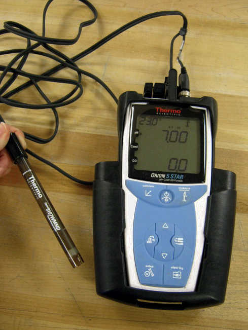
This specific pH of soils test is for uses other than corrosion testing. The test determines the degree of acidity or alkalinity in soil materials suspended in water and a 0.01 M calcium chloride solution. Measurements in both liquids are necessary to fully define the soil’s pH. The measurement of the pH of soils suspended in either water or calcium chloride solution is made with a potentiometer using a pH sensitive electrode system. The potentiometer is calibrated with buffer solutions of known pH. Reference ASTM D4972.
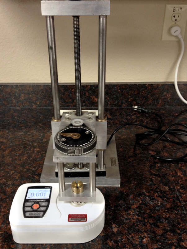
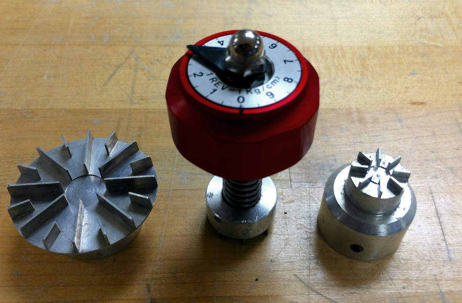
Pocket Penetrometer
The pocket penetrometer is used to find preliminary soil strength values and is used for classification of cohesive soils. It indicates consistency, shear strength, and approximate unconfined shear strength. The direct-reading scale is in tons per square foot or kilograms per square centimeter. This is typically used for stiffer soils. As a classification tool, it should not replace laboratory testing or field analysis, or be used to produce design data.
Qualitative Physical Description (Munsell Color Description, Soil Type, Foram Content, Water Content, Cohesion)
The qualitative physical description gives a wide array of descriptive information for classification of soils. Color is described with color codes from a Munsell color chart. Soil type is a grain size description characterized as clay, silt, sand, or gravel or a combination of those terms. Foram content, water content, and cohesion are all described relatively with terms such as low, moderate, or high.
Remolded Miniature Vane Shear
Remolded miniature vane shear testing is performed to determine shear strength in very soft to stiff saturated fine-grained clayey sediments. We use a set of 4 calibrated torsion spring sets combined with a motorized vane shear device to determine strength. The procedure is the same as Miniature Vane Shear except the sample is remolded first, breaking down any existing sediment structure. Reference ASTM D4648.
Specific Gravity
Specific gravity is the ratio of the mass of unit volume of soil at a stated temperature to the mass of the same volume of gas-free distilled water at a stated temperature. The specific gravity of a soil is determined by placing a certain mass of dry soil into a calibrated pycnometer and then filling the pycnometer with de-aired, distilled water under vacuum. Knowing the mass of the soil and the mass of de-aired water, the specific gravity of the soil solids can be determined. Reference ASTM D854.
Standard Resolution Photography
Standard resolution photography is used to capture visual representation of sediment characteristics. This type of photography can be used in conjunction with Qualitative Physical Descriptions (link) to gain a more complete understanding of sediment characteristics. It can also be used to document unique occurrences that cannot be adequately communicated with a written description. Photographs of this type are usually taken of a horizontal cross section of a core section.
Thixotropy
Thixotropy of soils describes when a remolded soil sample hardens over time while maintaining constant water content and constant volume. The gaining in strength is due to gradual reorientation of molecules and a regaining of the chemical equilibrium. This property is dependent on physical and chemical characteristics of the soil being tested and is performed over a 30-day period.
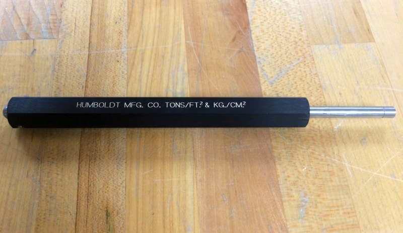
Torvane Shear
The torvane is used to find preliminary soil strength values and is used for classification of cohesive soils. This is typically used for softer soils and has adapters allowing it to accommodate a larger range of strengths. As a tool for preliminary testing, it should not replace a more precise strength measurement tool or be used to produce design data.
Unconsolidated-Undrained Triaxial (UU Triaxial)
UU Triaxial testing is performed to determine the shear strength of an undrained and unconsolidated cylindrical sediment sample. Specifically, the sample is placed under a confining pressure to simulate the condition of being confined by surrounding soil. The sample is then failed axially while measuring the force applied to the sample and the deformation. Measuring these two values allows us to construct a stress-strain plot of the failure. Reference ASTM D2850.
Unit Weight (Density)
Unit weight is a ratio of weight to volume. We can also report the density which is the ratio of mass to volume. The difference between the two values is only the acceleration due to gravity so one can be determined from the other. We use 2 different methods depending on the grain size. Unit weight and density testing is dependent on the specific soil structure and moisture content at the time of testing. Reference ASTM D7263.
If you would like to learn more about our geotechnical laboratory services and capabilities, please contact:
info@tdi-bi.com
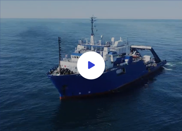
seabed geotechnical SURVEYS
TDI-Brooks offers offshore, nearshore, and inland marine geotechnical survey services using a suite of innovative tools for soil sampling and measurement. We also provide a comprehensive set of geotechnical analytical services for characterizing offshore samples.
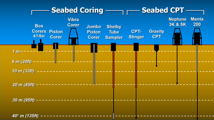
Our toolbox is designed for soil sampling and in‑situ measurements and includes box corers (BC), piston corers (PC), gravity corers (GC), jumbo piston corers (JPC), vibracorers (VC/pVC), a cyclic T‑bar instrument (TBAR), deep‑reaching Shelby tube samplers (SPLR), and piezocone penetrometers including our CPT‑Stinger and gravity CPT (gCPT) tools. Our vessels can also accommodate select third‑party geotechnical equipment packages. In addition to field operations, TDI‑Brooks provides soil testing through our in‑house geotechnical laboratory.
Our Geotechnical Toolkit provides high-quality soil samples and in-situ data from the following tools:
Geotechnical Toolkit (Highlights)
- 0.5‑ and 1‑meter Box Corer (BC)
- 40‑meter CPT‑Stinger (CPT)
- Dual Van Veen Grab Sampler
- 10‑meter Gravity CPT (gCPT)
- Auto‑Minivane System
- Neptune 3,000 Coiled Rod CPT System
- 1‑meter Cyclic T‑Bar Instrument (TBAR)
- Neptune 5,000 Coiled Rod CPT System
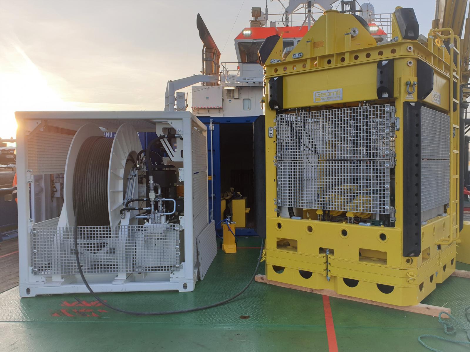
- Geomil Manta‑200 CPT System
- 6‑ and 9‑meter Piston Corer (PC)
- Feritech FT550 Vibracorer
- 20‑meter Jumbo Piston Corer (JPC)
- Multi‑Sensor Core Logger (MSCL)
- 40‑meter Stinger Sampler (Shelby Tube)
- Standard X‑ray CT System (XCT)
Download the TDI-Brooks Seabed Geotechnical Tool Kit Info HERE
Download the Seabed Geotechnical Flyer on our services HERE
Download the Seabed Geotechnical Coring Operations Video HERE
Contact us with any questions: info@tdi-bi.com
Auto T-Bar
Download the Auto T-Bar Flyer HERE
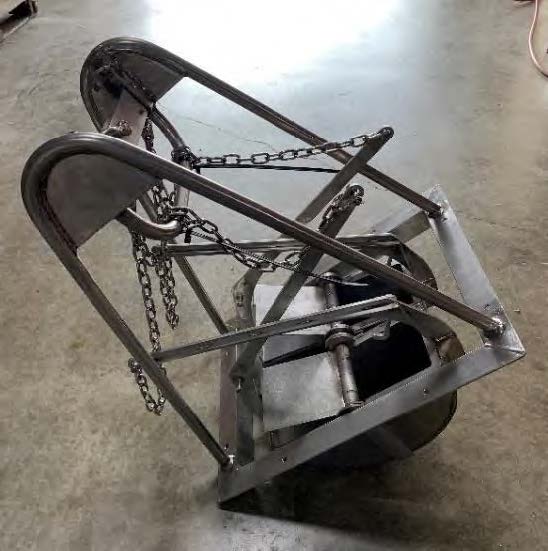
The TDI-Brooks Auto T-Bar instrument measures the progressive resistance of a soil column to a cylindrical rod (shaped as an upside-down T) as it advances down the soil column at a constant and standard rate of travel. The instrument is shown in Figure 9, with its T-bar protruding below.
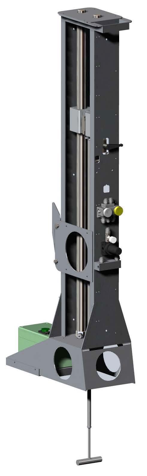
Operation consists of mounting the instrument onto a box corer containing an undisturbed seabed soil sample, connecting the instrument to a shipboard source of compressed air, and starting the automatic advance of the T-Bar into the soil sample. The resistance of the soil is automatically logged during the downward advance until the bottom of the soil sample is reached by the T-bar. The instrument then reverses T-bar movement and logs the soil resistance generated during the upward, retracing return of the T-bar back up to any desired soil depth or to the surface. This sequence of a downward stroke followed by upward re-trace through the failed soil can be continually repeated as many times as desired. Sets of 10 to 30 such cyclic T-bar tests are typical in box cores.
The instrument measures and logs the soil’s resistive force on the T-bar 10 times per second. The T-bar typically auto-advances at 2.0 cm/sec, so a data set is logged every 2 mm of penetration (this standard rate of advance can be changed to address differing client specifications). A single down-stroke test to 100 cm soil depth thus takes 50 seconds with 500 resistive force measurements logged (Table 1). The resistive force is reported in pounds or newtons, and is converted by the processing program into units of pressure (ksf or kPa) by dividing by the cylindrical cross-sectional area of the T-Bar. The standard (medium) T-Bar cylinder diameter is 1.00 in. and its length is 5.00 inches. Smaller T-bars (0.75 in. and 0.50 in. dia.) are also available for quick change-out, each with cylinder length 5 times its diameter. The push rod is sleeved, rendering its frictional drag during advance in either direction to have no measureable component. The calibrated range of the tool is -100 lb (445 N) upstroke to +100 lb downstroke, which translates using an Nt-bar of 10.5 to maximum measureable undrained shear strengths of about 275 psf (13.2 kPa) using the large bar, 500 psf (23.9 kPa) for the medium bar, and 1,100 psf (52.7 kPa) for the small bar. An example of 30 cyclic auto T-bar measurements into a 1m deep box core sample are plotted in the figure below.
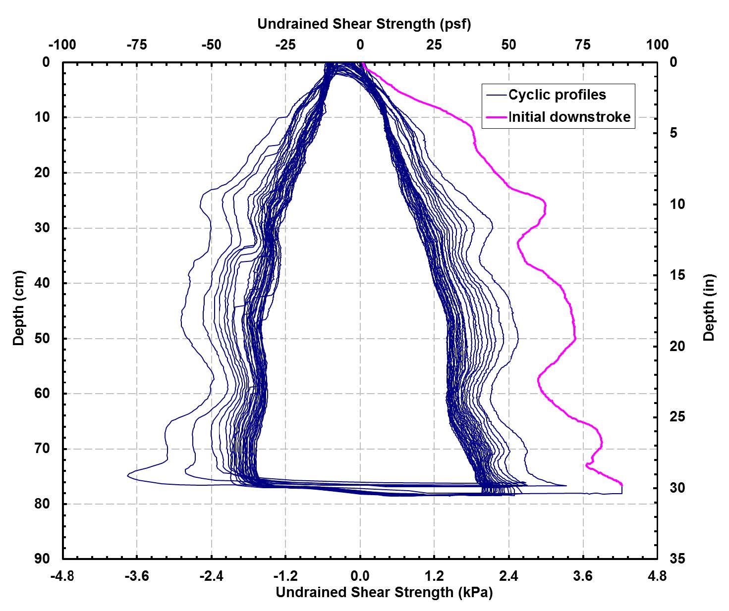
In this figure, the pink trace represents the initial downward stroke of the T-bar into the soil. The two (right and left) nested sets of blue traces are the subsequent progressive upstroke and downstroke data, with the inner traces being the 30th and final stroke set. All measurements have been converted using an Nt-bar of 10.5 to represent undrained shear strength. This plot illustrates the progression of soil reworking toward fully remolded character during the course of the 30 sets of strokes. Such a data set can thus be also used to project fully remolded values at selected soil depths.
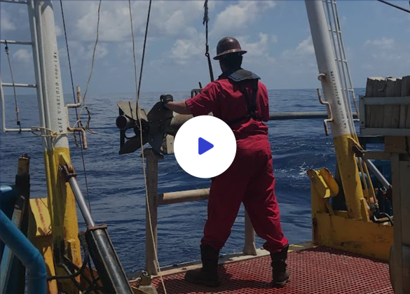
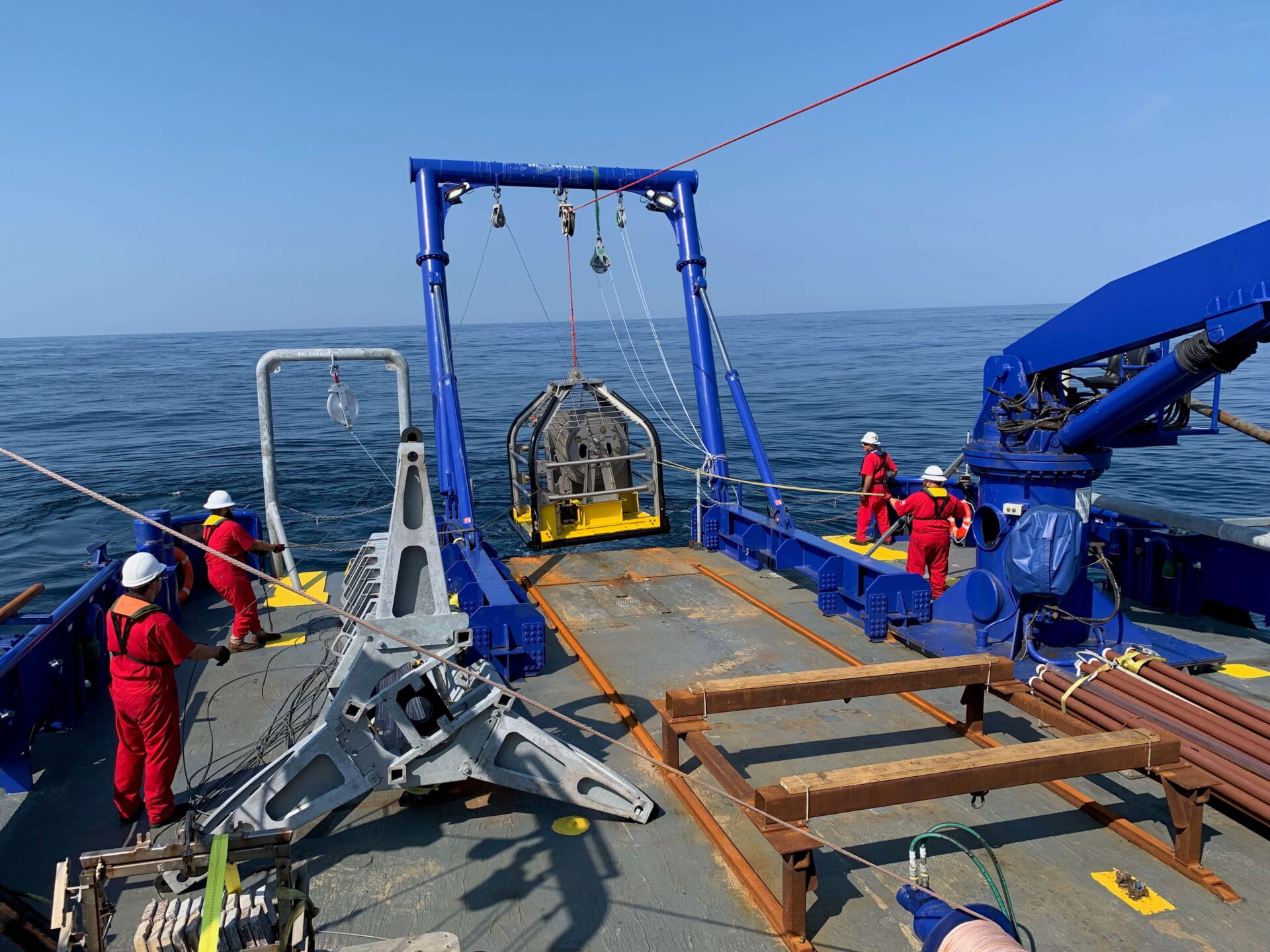
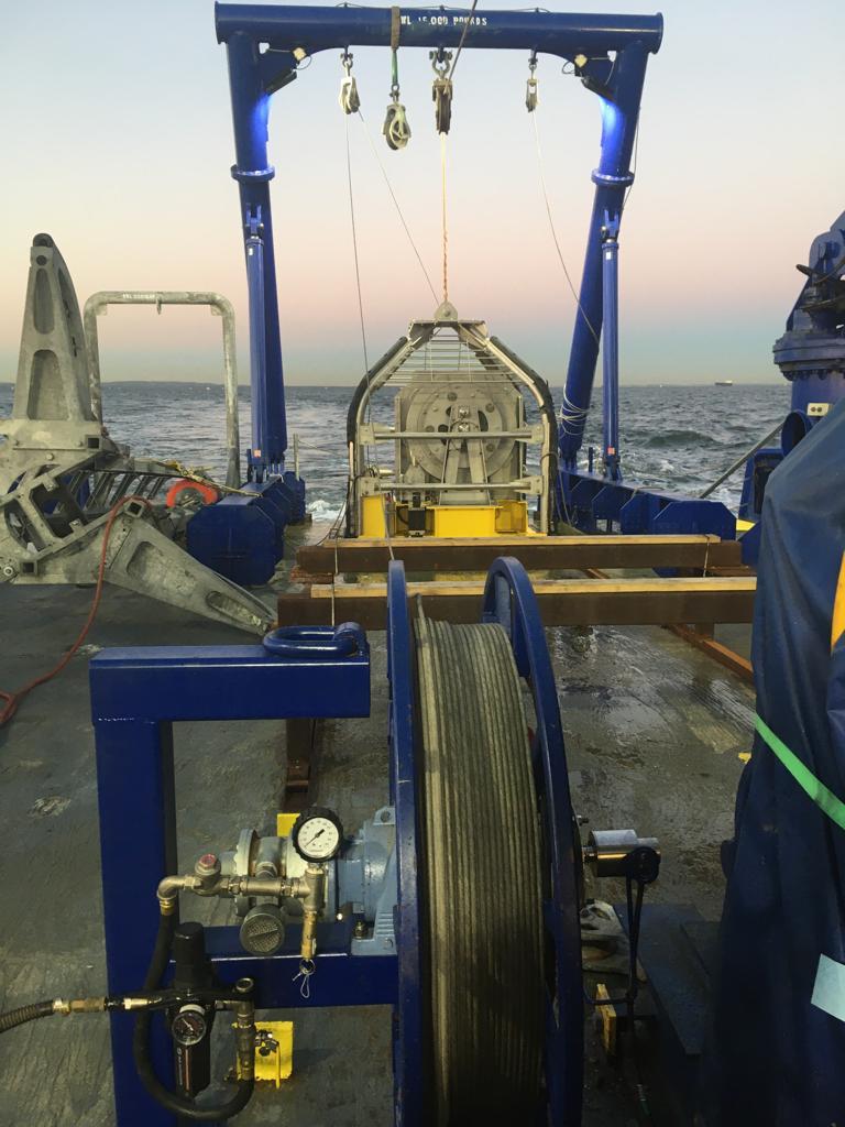
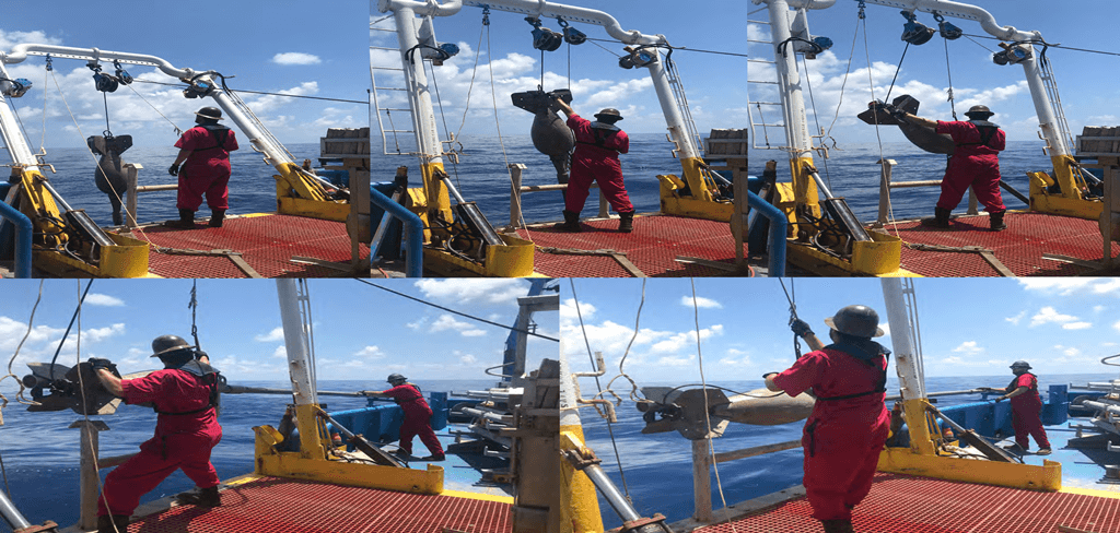
Box Coring
Download the Box Core Flyer HERE
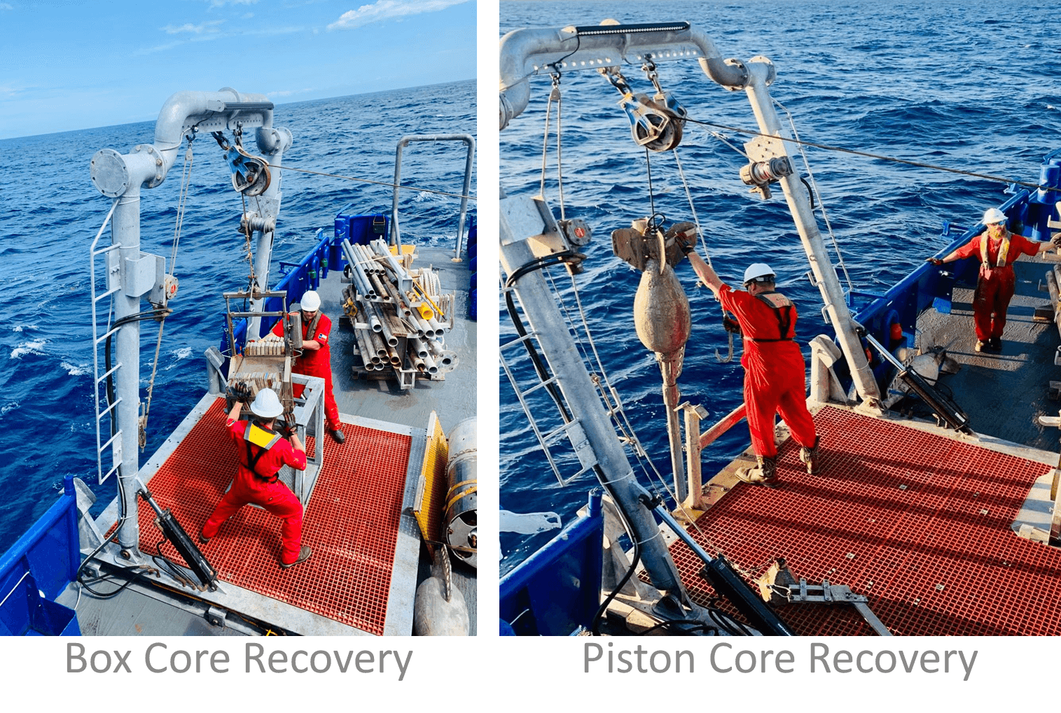
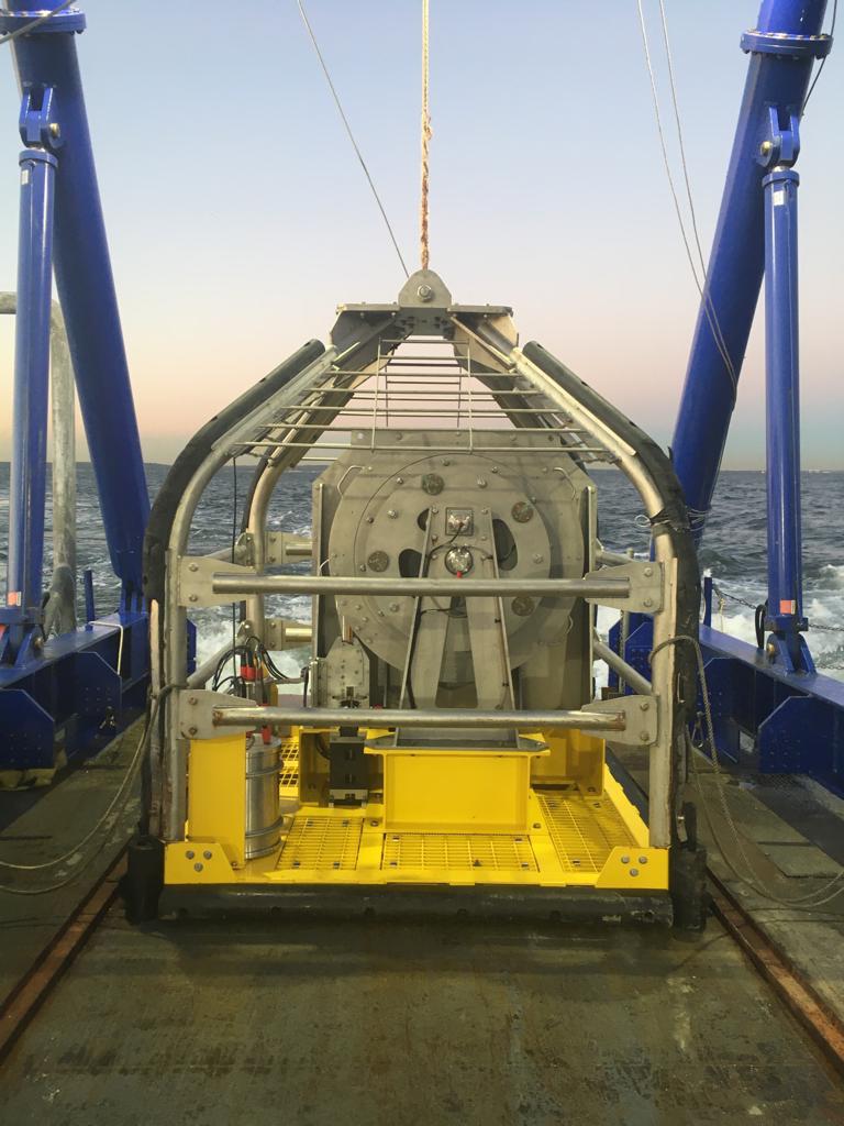
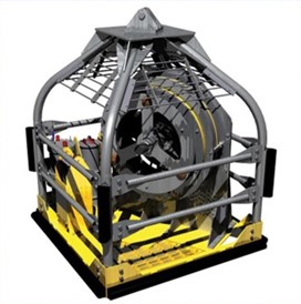
The TDI-Brooks box coring system consists of hardware assemblies designed to be rigged together into a working core rig and deployed to the seabed for extracting a standard cubic box core. Such a core is 100-cm (depth) x 50-cm x50-cm or 50-cm (depth) x 50-cm x50-cm in size. The main winch, main coring rope, and the starboard A-Frame are used for deploying and retrieving the box core rig.
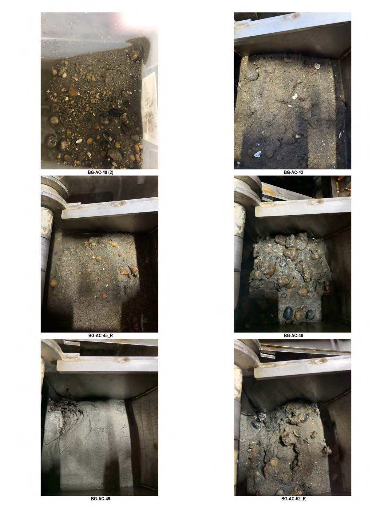
Our box coring system is designed to be a safe, simple, effective mechanism for acquiring large-volume undisturbed shallow sediment samples from the seabed. Such samples are essential for the accurate determination of geotechnical characteristics of marine sediments and the assessment of the benthic ecology (infauna) as required in environmental impact assessments.
The sample box of the core rig is fabricated from stainless steel and is clean and smooth to minimize frictional resistance between the box and the sediment. The corers have a variable weight capability so that the weight stack can be adjusted to suit different seabed conditions that may be encountered.
CPT Stinger
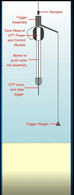
The CPT-Stinger is installed in a JPC core-head, deployed and triggered with the well-proven TDI-Brooks JPC process, and allowed to free-fall ballistically to insert itself into the sediment like a JPC. Once fully embedded in the seafloor with the necessary resulting reaction force now available, the CPT-Stinger is programmed to extend a rod from inside the barrel deeper into the formation (like a stinger) at the standard ASTM (static) cone push rate.
The CPT Stinger can be inserted to about 72 ft BML (while gathering dynamic CPT data) and then used to push a cone penetrometer to about 135 ft BML while gathering static CPT data. Because the extended rod is essentially as long as its barrel, in-situ CPT data can be acquired to sediment depths double of that of the barrel length of the tool (or of a corresponding JPC).
The CPT Stinger has its own engineered barrel assembly, internal rod set, control module, and PCPT cone with data logger. The rig is deployed in the same manner as if acquiring a JPC. After trigger less than 1 m above the seabed, the dynamic cone data are acquired at a high rate during ballistic penetration into the formation.
After penetration to full embedment, the cone data acquisition continues while the cone is slowly pushed deeper into the formation at a constant rate.
During this push phase, the probe advances at a controlled ASTM rate of 2.0 cm/sec ± 0.5 cm/sec. Data from the probe are logged as the push progresses. Once complete, the system is retrieved to the vessel and data are downloaded from the probe for evaluation and analysis. The tool is then readied for the next deployment, typically in less than 20 minutes, making 3 to 5 deepwater deployments per 12-hour day routine.
The maximum water depth for the CPT Stinger is 3,000 m, but special 4,500 m cones are also available for ultra-deep tests. The tested minimum water depth for the CPT-Stinger is currently 350 m, though a shallower water capability may be possible.
Dual Van Veen Grab Sampler
Download the Dual Van Veen Grab Sampler Flyer HERE
The Dual Van Veen Grab Sampler is designed for collecting sediment samples in fresh and marine water, from soft or medium-hard bottoms like sand, gravel, consolidated marl or clay.The double grab configuration allows for more efficient sampling operations in deeper waters, reducing the time needed on the vessel. The system is suitable for projects in both shallow and deep waters.
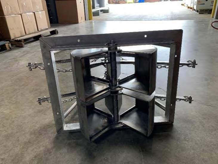
The Double Van Veen Grab is designed for comparable sampling where samples for chemical and also biological analysis are required from the same site. The grabs are mounted on a common pivot and each bucket has the capacity to collect a sample of approximately 0.10 m2 . Similar to the Salish Sea design the double Van-Veen comes with a weight frame and release mechanism which makes it ideal for hard substrates such as clays and gravels. During the descent, the two buckets remain apart. When it hits the bottom, the locking mechanism releases, and when the main line is pulled to retrieve the grab, the buckets close allowing the collection of the sample.
The sampling device is composed of two 0.04 m2 samplers (.08 m2 total) joined together in a single frame. The target penetration depth is 0.1 m, which is the nominal limit of the grab sampler. One sample can be collected for benthic infauna (one side of the grab) and the 2nd side of the grab for geotechnical measurements at each site. A grab sample is deemed successful when the grab unit is > 75% full (with no major slumping). The grab sampler is recovered from the seabed and back onto the vessel at a velocity which minimized any potential loss or disturbance to the seabed sample.
ferritech ft 550 vibrocorer
Download the Ferritech FT550 Vibrocorer Flyer HERE
Feritech’s vibrocorer is one of the most versatile on the market, with its modular construction, high power variable frequency, sensor capabilities, and software control.
The 3rd generation FT550 lightweight variable frequency high power vibrocorer leads the market in its technical innovation and performance.
Product Highlights:
Variable frequency of 5 – 50Hz
- High power with up to 75kN thrust
- 1 – 12m modular construction (in 1m increments)
- Rapid mobilisation with plug and play setup
- Change barrels with the frame laid horizontally or vertically
- 2:1 mechanical advantage on lifting wire aiding barrel extraction
- Quick barrel release system
- 300m – 7000m depth rating available
- Stable operation in up to 10 knot currents
- Consumables compatible with Feritech Global gravity and piston corers
- Frame hot dip galvanised to BS EN ISO 1461:2009
The subsea equipment is built to withstand the harsh offshore environment and unforgiving handling. The topside software informs the engineer of the information he needs to ensure efficient, successful and safe deployment and operation. Due to its simple-to-assemble modular construction, the system can be mobilized very quickly for cores of 1-12m.
Variable frequency and thrust Feritech Global’s vibrocorer is the only system on the market with an integrated high power varible frequency system. By using this unique variable frequency system, sample disturbance is minimised, ensuring a high quality sample regardless of high power settings.
Unlike any other vibrocorer system, the Feritech vibrocorer can be deployed and recovered to deck in the horizontal or vertical axis, meaning that the user can choose the best deployment and recovery method for the vessel they are operating from. The quick release barrel system ensures a fast barrel change optimising operational equipment time. A barrel can be changed in a matter of minutes, whether the system is being deployed in horizontal or vertical mode
With its modular construction, the entire FT550 system and spares can easily be packed into a standard 20 foot ISO shipping container.
The FT550 has a proven track record of quickly penetrating consolidated sediments. The variable frequency has been used time and time again to acquire high quality core samples from stiff clays, compacted sands, to sites with chalk and gravel.
The magCORE adds the ability to see oncoming ferro-magnetic obstructions within the ground. Thtis has many uses from UXO (unexploded ordnance) detection to measuring the depth of sheet piling or other metallic foundations.
The sensors measure in 3 dimensions and so can detect a target both in front of and to the side of the barrel.
The topside controller shows the engineer the information he needs to ensure an efficient, successful and safe deployment and operation. The rugged topscreen unit displaying and logging real time data from the system for the user, including:
- Penetration distance and rate
- Depth sensor
- Inclination
- Settlement into seabed
- Altitude from seabed
- Frequency and power
geotechnical portable 3rd party Tool Kits
TDI-Brooks offers offshore, nearshore, and inland marine geotechnical survey services using a suite of innovative tools for soil sampling and measurement, including box corers (BC), piston corers (PC), gravity corers (GC) and jumbo piston corers (JPC).
We have the following portable geotechnical took kits for use on a 3rd party vessel:
- Light coring kit: PC, BC operations. Available Winch, Control House, Track, A-frame components additionally.
- Heavy coring kit: PC, BC, JPC, CPT operations. Available Winch, Control House, Track, A-frame components additionally
Contact us with any questions: info@tdi-bi.com
Gravity CPT (gCPT)
Download the gCPT Flyer HERE
The purpose of the TDI-Brooks Gravity CPT (gCPT) tool is to transport a precisely calibrated memory cone penetrometer down to the seabed/lakebed to gather dynamic PCPT cone data from the mud line to 10+ m BML. In addition to its 1,800 lb (800 kg) driving head with lifting bale and trigger, the rig comprises a self-contained PCPT cone penetrometer that measures tip resistance (qc), sleeve friction (fs), and pore pressure (u2) using standard ASTM dimensions and protocols for its 15 cm2 cone.
The gCPT system is efficiently deployed using the same winch, A-frame, deployment kit, and procedures as for standard piston coring. The tool is triggered to ballistically insert itself into the soil using downward momentum (freefall) generated by gravity. All cone channels are logged 200 times per second during this process, including calibrated acceleration for precise velocity, penetration, and tilt.
Once the cone insertion into the soil is complete (within 5 sec after trigger), the tool’s precise location is recorded (using USBL when in deepwater), and then the tool is retracted from the soil and retrieved to the deck. Cone data are immediately downloaded from the probe for evaluation and analysis. The tool is readied for the next deployment, typically in less than 5 minutes, making numerous measurements per day feasible, depending only on water depth and winch speed. The maximum water depth for the gCPT system is 3,000 m, but special 4,500 m cones are also available for ultra-deep tests. High quality in situ dynamic PCPT data can be rapidly acquired from the mudline to 30+ft (9+m) below the mud line in a safe, rapid, and cost-effective manner. Probe data are logged 200 times per second. This logging rate allows the cone parameters to be measured at sediment intervals no larger than 2-5 cm even at ballistic advance velocities reaching up to 10+ m/sec.
Parameters logged include tip resistance (mPa), sleeve friction (kPa), pore pressure (mPa), cone acceleration (m/s2) and cone tilt (°) from vertical. We calibrate and adjust these dynamic cone data to static PCPT data-equivalent using our proven and calibrated database of cone rate effect measurements with soil type. Adjustments due to the advance rate effect are slight for tip resistance and sleeve friction, and negligible for pore pressure. Comparisons between side-by-side static PCPT data (2 cm/sec ASTM-rate cone advance) with the rate adjusted dynamic PCPT data acquired during the tool’s insertion have been remarkably good for more than 400 sites in our international database.
More info on Gravity CPT HERE
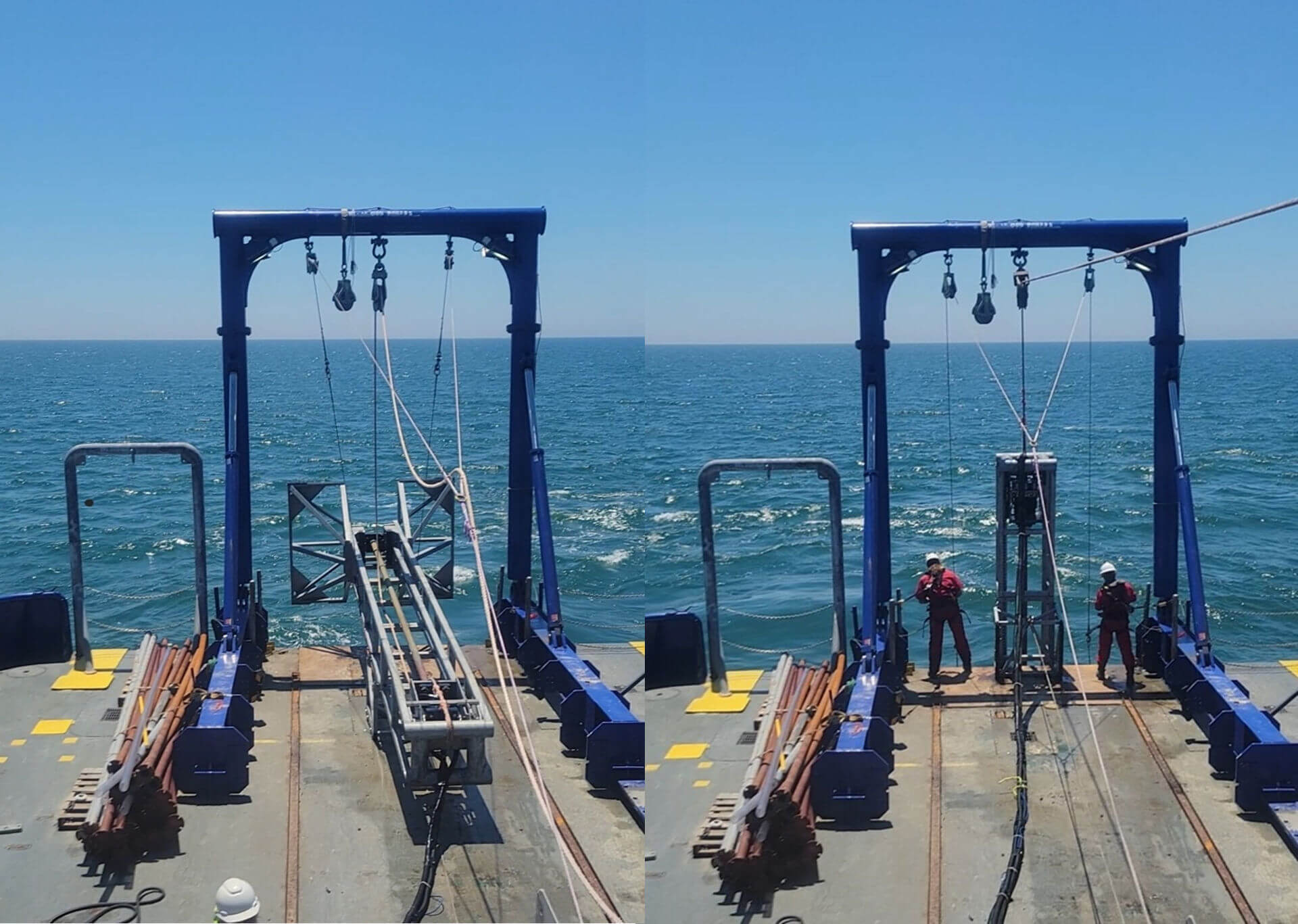
Jumbo Piston Coring
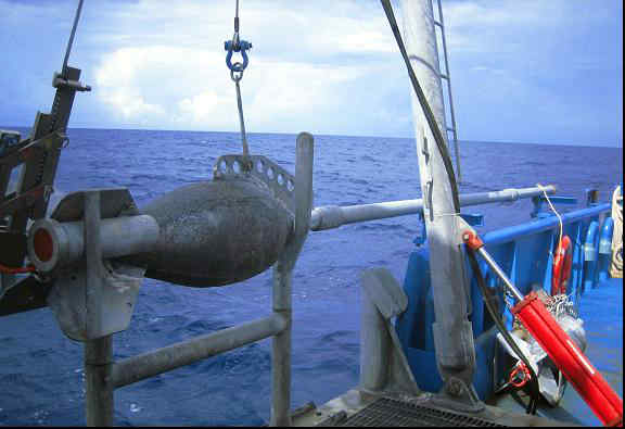
The TDI-Brooks jumbo piston coring (JPC) system consists of various hardware assemblies designed to be fastened together into a working core rig and deployed to the seabed for extracting a “jumbo” piston core. The deployed core rig comprises assemblies for the core head, the core barrel, the piston, and the trigger system. The JPC rig can be assembled to collect a sample up to 64 feet long. There is also lifting assembly that attaches to the trigger system, allowing the system to be deployed with an A-frame. The core barrel assembly is made up of selected sections of core barrel, connecting collars, a core liner assembly inside the barrel assembly, a core catcher, a core cutter, and set screws to hold the barrel assembly together. The inner diameter of the core liner is 4 inches. The barrel length can be adjusted in 5-foot and 10-foot increments by adding barrel sections and connecting collars. The trigger assembly is made up of the trigger arm, pendant clamp, trigger weight, trigger wire, and trigger wire connecting system. The assembled core rig weighs between 5,500 and 7,000 lbs, depending on the length of core to be acquired. The weight of the core head is adjusted by adding weight as lead ingots to a starting weight of about 5,000 lb.
The main winch, main-line rope, and the stern A-Frame are used for deploying and retrieving the JPC rig. In addition to the deployed hardware, several assemblies are mounted to the vessel working deck to manage the deployment and retrieval of the coring rig. These assemblies include the main sheave from the stern A-Frame and the deployment, retrieval and trigger tugger winches with their hydraulic power pack.
Manta-200 CPT System
Download the Manta-200 CPT Flyer HERE
The TDI-Brooks’ Manta-200 Cone Penetration Testing (CPT) system is suitable for almost any project in shallow water up to 150 meters. The CPT system is powered by a unique Continuous Drive System (CDS) that was designed with a clear focus on durability and high production. It also guarantees uninterrupted penetration of the cone.
The Manta-200 CPT system is a modular design capable of delivering results on even the most challenging of projects with a chain-drive based system that can reach penetration depths of up to eighty meters. Both casings and tubes can be operated simultaneously.
During CPT operation the Manta is controlled from the surface with a real time link over a combined power and communication umbilical. Data can be viewed in real time allowing operators to manage the push and react to local sediment conditions to provide the highest quality data to the greatest depths possible.
The Manta system is composed of the base equipment which is then completed with supporting options like ballasts and winches all depending on your project’s requirement. The heart of each system is its capability of retrieving and processing high quality data. During CPT operation the Manta is controlled from the surface with the control box. The controls are intuitive and easy to use. Data is viewed in real time as with a conventional CPT. Data, communication and power are all handled by the umbilical.
The Manta-200 measures 2,200 x 2,200 x 2,300 mm(L x W x H) when being transported. The basic setup is transportable in 20 ft sea containers.
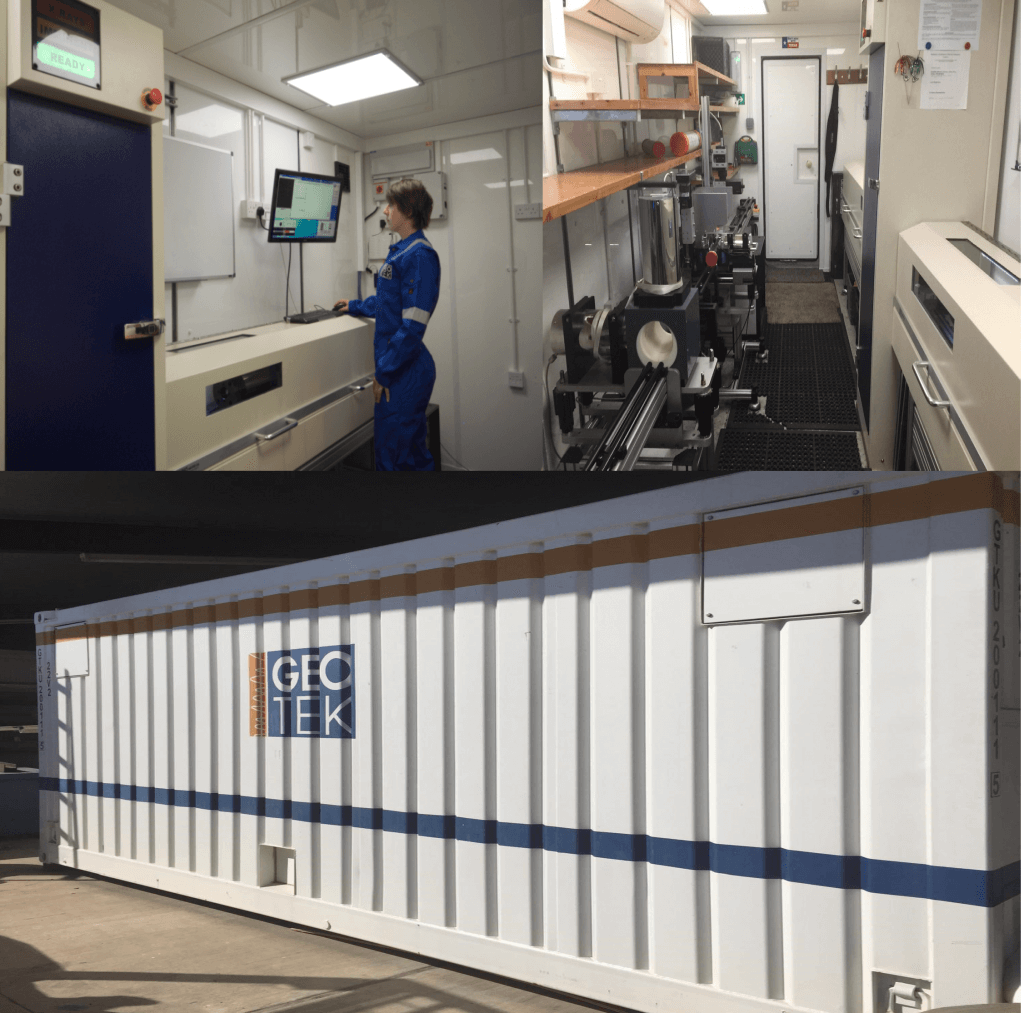
MULTI-SENSOR CORE LOGGING (MSCL)
MSCL systems rapidly and non-destructively obtain high-resolution (typically 1 cm to 10 cm downcore spacing) geophysical and geochemical data from sediment and rock cores. The high quality multi-parameter stratigraphy delivered from MSCL systems enables facies classification and soil/rock typing ahead of, or in support of a visual description. Ultimately this leads to improved laboratory test planning for any necessary destructive or advanced laboratory testing. The Geotek core logging services team follows strict calibration procedures for each core size and liner type to ensure consistency and accuracy of data collection.
Sediment or rock cores with or without metal or plastic liners up to 1.5 m long and 155 mm in diameter can be accepted. Physical, elemental and mineralogical properties can be obtained from whole or split/slabbed core samples regardless of whether they are within a liner or not. An MSCL dataset provides vital information about core heterogeneity or homogeneity ahead of destructive laboratory testing or visual logging.
More details here: TDI-Brooks Partners With Geotek UK to Deliver Expanded Services – TDI-Brooks International (tdi-bi.com)
neptune 5,000 Coil Rod CPT System
Download the Neptune 5K CPT Flyer HERE
The Neptune 5000 Heavy Duty CPT System is a coiled rod Cone Penetration Test System featuring a 35kN Push capability with a coiled tubing CPT system that is easy to mobilize.
The system has a maximum penetration of 20 meters with real time control and data acquisition and built-in automatic safety cut-outs making it perfect for the renewables market.
- 5cm² Detachable Cone, 10cm² Cone and T-Bar Cone
- 35kN Push Capability
- Up to 20m Penetration from Coiled Rod
- Easily Deployed Compact Sub-Sea Frame
- Real Time Control and Display
- Single Coax Connection for Power and Data
- Automatic Safety Cut-Outs
- Low Maintenance, Low Consumable Use
- Easy to Operate Windows™ based PC Control
This highly advanced equipment is designed for thrusting 5 cm² or 10 cm² Digital Cones. The unit can thrust up to a maximum of 70 MPa and has a depth rating of 3000 meters. This is an excellent tool for investigating seabed conditions prior to seabed installations such as pipelines, power cables and underwater constructions. The measurements comprise of penetration depths, cone resistance, sleeve friction, pore pressure and inclination from vertical.
The system can be mobilised to a variety of vessels depending upon the nature of the project, ranging from the fuel efficient vessels at 30m LOA, to regular charter vessels upwards of 50-70m LOA. The high mobility and small footprint of 2.2m x 2.2m makes it perfect to be mobilized onboard vessels of opportunity.
The 5000 is fitted with 5cm or 10cm Digital Piezocones and benefits from self-tuning telemetry. The surface controls unit operates a Microsoft Windows PC combined with the established Neptune software package, providing real-time data.
neptune 3,000 Minature Coiled Rod CPT System
Download the Neptune 3K CPT Flyer HERE
The TDI-Brooks Datem Neptune 3000 Miniature Coiled Rod CPT System is a coiled rod Cone Penetration Test System featuring a 10kN Push capability. This lightweight coiled rod CPT system is for use in up to 3000 meters of water and designed to withstand the harshest of sea environments.
A coiled tubing CPT system that is easy to mobilize, featured coiled rod system enables the Neptune 3000 to be self-contained and compact, therefore allowing the system to be deployed from the smallest of survey vessels where space is often of a premium. This CPT unit is commonly used for pipeline surveys for oil and gas operators and cable route surveys for offshore renewables.
- 2cm² Detachable Cone, 5cm² Detachable Cone and T-Bar Detachable Cone
- 10kN Push Capability
- Up to 10m Penetration from Coiled Rod
- Compact and Easily Deployed Sub-Sea Frame
- Real Time Control and Display
- Single Coax Connection for Power and Data
- Automatic Safety Cut-Outs
- Low Maintenance, Low Consumable Use
- Data Comparable to 10cm² Systems
- Easy to Operate Windows™ based PC Control
The Neptune 3000 CPT enables its operators to perform an in-situ real-time test of the subsea soil structure therefore eliminating/reducing the requirement for time intensive soil sample extraction, storage and examination, thus reducing project duration and therefore cost.
The system uses Datem’s digital 2cm cones, 5cm cones and T-Bar cones to suit all subsea soil conditions, providing axial load, sleeve friction, pore pressure, dual axis tilt and temperature data in real time (selectable up to 20hz) as they penetrate through the soil with data comparable to that of 10cm cones. With a push force of up to 10kN and a maximum push distance of 10 meters the Neptune 3000 is an industry renowned and hugely popular CPT system globally.
Piston Coring
Download the Piston Corer Flyer HERE
The TDI-Brooks 3-inch-diameter (3-in.) piston coring system consists of various hardware assemblies designed to be fastened together into a working core rig and deployed to the seabed for extracting a piston core. The PC rig can be assembled to collect samples up to 30 feet long and collects a 3 inches diameter sample. The deployed core rig comprises assemblies for the core head, the core barrel, the piston, and the trigger system. The core head assembly is made up of a lead-weighted core head with nosepiece and a coupling with which to attach lengths of core barrel sections. It also has a lifting flange assembly that attaches to the trigger system. The trigger assembly is made up of the trigger arm, pendant clamp, trigger weight, trigger wire, and trigger wire connecting system. The core barrel assembly is made up of selected lengths of core barrel sections, connecting collars, a core liner inside the barrel assembly, a core catcher, a core cutter, and set screws to hold the barrel assembly together. The barrel length can be adjusted in 5-foot increments by adding 5 or 10-ft barrel sections and connecting collars.
The main winch, main-line coring rope, and the starboard A-Frame are used for deploying and retrieving the 3-in. piston core rig. In addition to the deployed hardware, several assemblies are mounted to the vessel working deck to manage the deployment and retrieval of the coring rig. These assemblies include the main sheave from the starboard A-Frame and the core-head and trigger tugger winches with their hydraulic power pack.
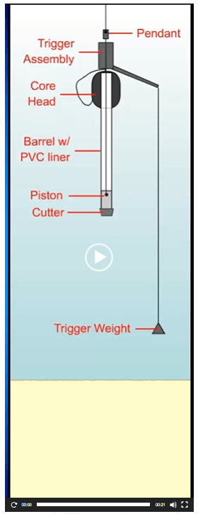
A piston corer uses a free fall of the coring rig to achieve the desired initial force on impact, and a sliding piston inside the core barrel to reduce inside wall friction with the sediment and to assist in the rapid evacuation of displaced water from the top of the corer. These elements act in concert to maximize core recovery.
tdi-brooks pneumatic vibracorer
Download the Pneumatic Vibracorer Corer (pVC) Flyer HERE
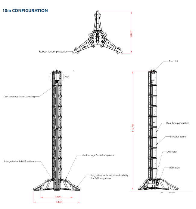
The TDI-Brooks Pneumatic Vibracorer (pVC) is a lightweight high power vibracorer. The pVC can be used for cores of 1 to 6 meters (and down to 12-m with frame extension). The topside display informs the winchman of the exact penetration of the core barrel into the soil at any point during its vibrating insertion.
Vibracorer Technology
Vibracoring is a technique for collecting core samples of seabed sediments and wetland soils. The core barrel is incrementally driven into sediment aided by gravity, using an asymmetric pulsing energy imparted to the barrel from the vibrating head. These pulses are generated by a pneumatic pressure drop across the head, which produces mechanical pulses (hammer blows) in the downward direction at a 10-20 Hz rate. The pulses cause a thin layer of material to mobilize along the outer barrel wall and the inner core liner wall, reducing friction, easing penetration into the substrate, and aiding recovery of the soil material into the liner.
Although vibracoring is not a system for hard material, like drilling, it has become the industry standard for the collection of environmental and sedimentological samples in shallow marine depositional environments. This is partly due to the efficiency of vibracoring – with cores up to 6 meters retrievable in 10 minutes, but also due to the high recovery of vibrated samples. In loose soils, recovered core lengths can approach full barrel penetration depth. In stiffer soils, less than half penetration depth is recovered from less than full penetration, as the liner plugs with soil and stops the movement of the core material up the liner. For marine environmental studies – particularly where chemistry is needed, the higher recovery of sediments is critical in understanding the history of the deposited sediments. The down-side of vibrating soil material to achieve greater core recovery is that the sample collected will likely geotechnically disturbed.
Pneumatic Vibracorer Origins
Some of the earliest designed vibracorers came from the construction industry using impact hammers and vibratory motors to run pile drivers. Early versions were frequently driven mechanically and as techniques progressed and adapted to the marine environment the approach migrated to air driven systems. This offered more flexibility and mechanical simplicity for usage underwater and allowed operation from more mobile, smaller vessels. The downsides being water depth limitations due to hose constraints and loudness both on the boat and in the water.
The subsea equipment is built to withstand the harsh offshore environment and unforgiving handling. It is designed for safe deployments and retrievals using a robust process from the stern of the vessel. Operations are safely conducted by a winchman, an a-frame operator, and two deckmen. Due to its simple-to-assemble modular construction, the system can be mobilized very quickly for cores of 1-6-m.
- Vibrator Type: Pneumatic impacting piston vibrator
- Air Consumption: 250CFM @120psi
- Frequency: 600-1200 bpm
- Waveform: asymmetric Impacting
- Tool Dimensions in standard 6m configuration: 292″ Tall x 82″ x 105″
- Tool Weight in air: 4,600lb
- Tool Weight in water: 3,900lb
- Stroke in standard 6m configuration: 5.75m
- Liner ID: 2.75″
- Cone Barrel ID: 3.0″
- Cone Barrel Wall: 1/8″
- Penetration Measurement: 5cm resolution, real time display at winch
- Water Depth Rating: 75m
- Maximum Core Length: 5.75m
- Lifting frame: 15,000lb crane/winch and a-frame
- Power requirement: 440V ø3 300KVA start / 100KVA run
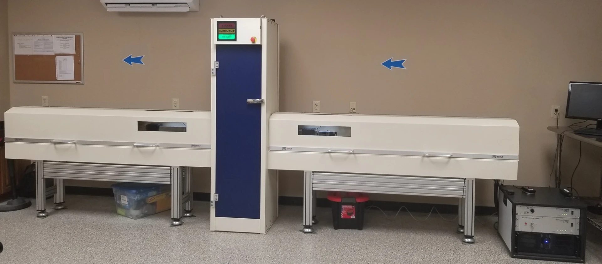
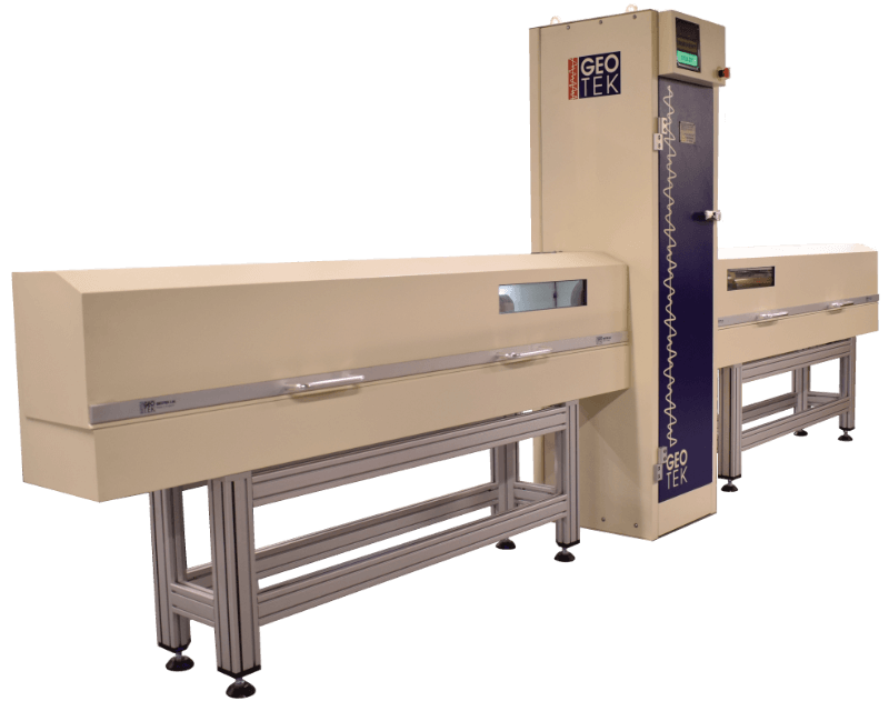
XCT: Standard X-Ray CT System
TDI-Brooks has a Geotek XCT system on campus to acquire both 2D X-ray transmission images and 3D X-ray CT volumes from lined whole core, split core, or slabbed core sections. Automated rotation of lined core sections allows users to visualise and record three-dimensional structures within the cores. These rotational images are used for computed tomographic (CT) reconstructions. X-ray CT imaging provides valuable quantitative data as well as information about core quality for sub-sampling or further analyses. More details here: TDI-Brooks Partners With Geotek UK to Deliver Expanded Services – TDI-Brooks International (tdi-bi.com)
Stinger Shelby Tube Sampler
The high cost of conventionally drilled borings in deepwater limits the number of borings that can be drilled, the number of soil samples that can be collected, and the areal coverage for a given project. To remediate the situation, TDI-Brooks has developed and is now offering an innovative and cost-effective tool called the Stinger Sampler. The basic idea behind the deepwater Stinger Sampler system is to “transport” a Shelby tube down through the seabed to acquire geotechnical-quality core samples down to depths of 20 to 40 m BML, thus nicely complementing the 0-20m continuous JPC soil samples.
The economic benefits of quickly acquiring from a modest-cost vessel several high-quality geotechnical soil samples are readily apparent, in that the Stinger Sampler allows more high-quality data to be acquired for a given budget, and affords more areal coverage compared to the amount of data obtainable from a single, more expensive conventional soil boring. Thus, the Stinger Sampler helps reduce the overall risks associated with foundation design and installation planning.
Download the Stinger Shelby Tube Sampler Flyer HERE