Field Acquisition Services
seabed Geotechnical surveys
seabed geotechnical SURVEYS
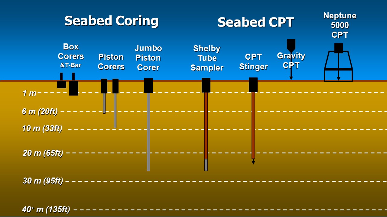
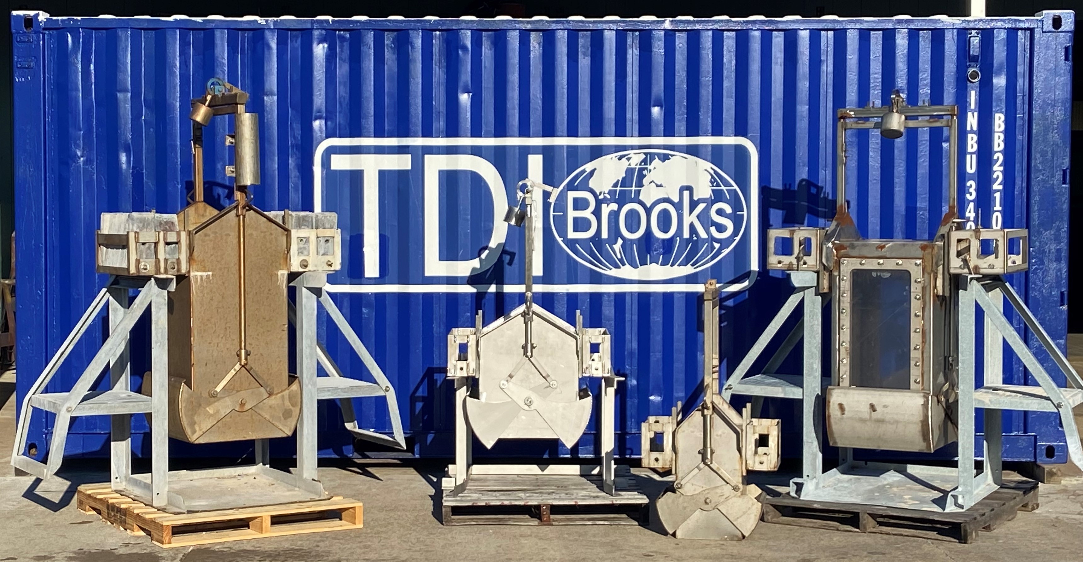
TDI-Brooks offers offshore, nearshore, and inland marine geotechnical survey services using a suite of innovative tools for soil sampling and measurement. We have developed a suite of geotechnical analytical services for characterizing offshore geotechnical samples. Our suite of innovative geotechnical tools are for soil sampling and measurement and including box corers (BC), piston corers (PC), gravity corers (GC), jumbo piston corers (JPC), vibracorers (VC/pVC), cyclic t-bar instrument (TBAR), deep-reaching Shelby tube samplers (SPLR), and piezocone penetrometers including our CPT-Stinger, Gravity CPT tools (gCPT)..
Our vessels can also be used to accommodate some third party geotechnical equipment packages. In addition to our offshore geotechnical sampling tool kits, TDI-Brooks can provide soil testing services through our in-house geotechnical laboratory.
Our Geotechnical Toolkit provides high-quality soil samples and in-situ data from the following tools:
|
• 0.5 and 1 meter Box Corer (BC) • 0.5 and 1 meter Box Corer (BC) • 6 and 9 meter Piston Corer (PC) • 20 meter Jumbo Piston Corer (JPC) • 1 meter Cyclic T-Bar Instrument (TBAR) • 40 meter CPT Stinger (CPT) • 10 meter Gravity CPT (gCPT) • 40 meter Stinger Sampler (Shelby Tube) • Miniature Vane Systems |
• Ferritech FT 550 Vibracorer • TDI-Brooks Pneumatic Vibracorer (pVC) • Neptune 3,000 Coil Rod CPT System • Neptune 5,000 Coil Rod CPT System • Manta-200 CPT System • Multi-Sensor Core Logger (MSCL) • Standard X-Ray CT System (XCT)
|
Download the TDI-Brooks Seabed Geotechnical Tool Kit Info HERE
Download the Seabed Geotechnical Flyer on our services HERE
Download the Seabed Geotechnical Coring Operations Video HERE
Contact us with any questions: info@tdi-bi.com
Auto T-Bar
Download the Auto T-Bar Flyer HERE
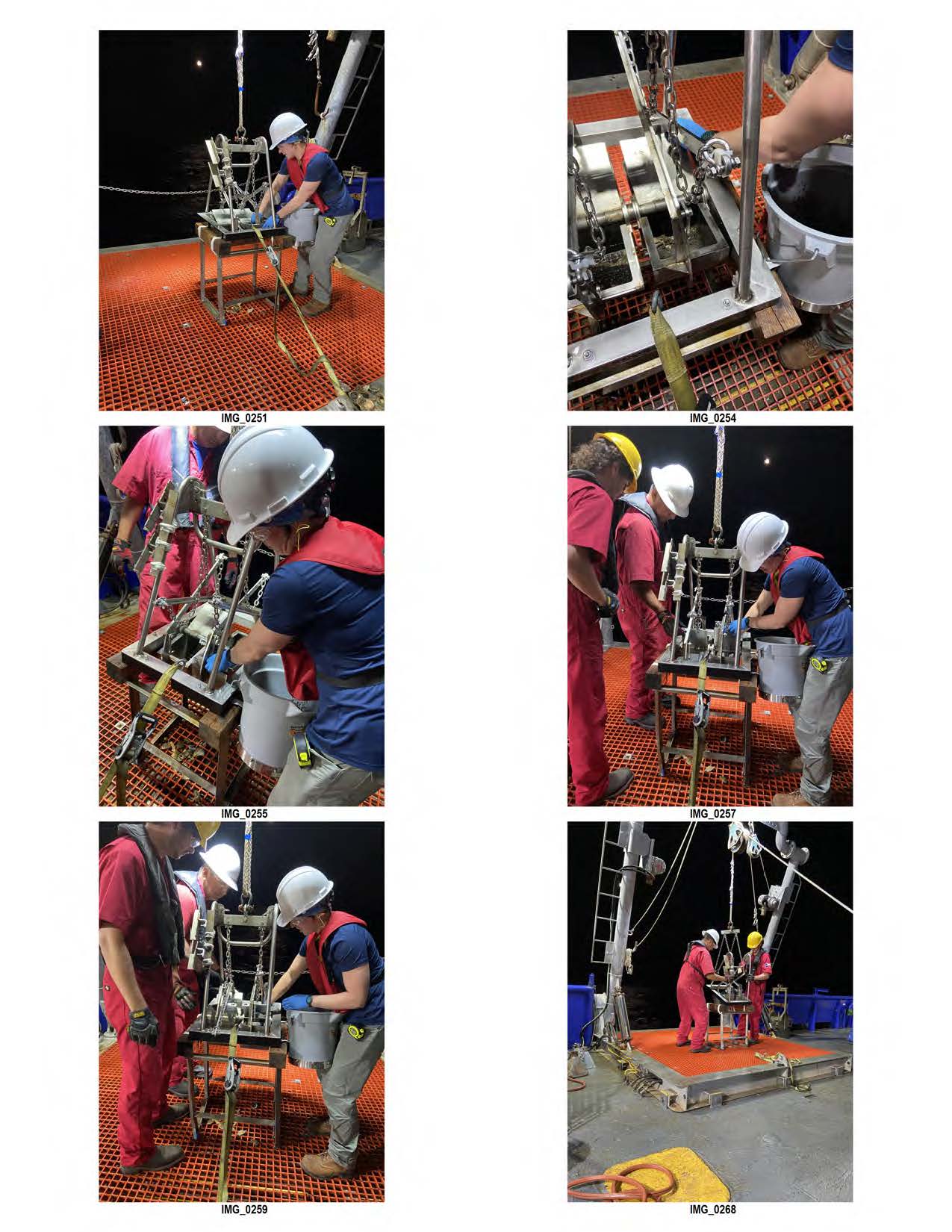
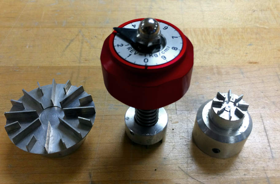
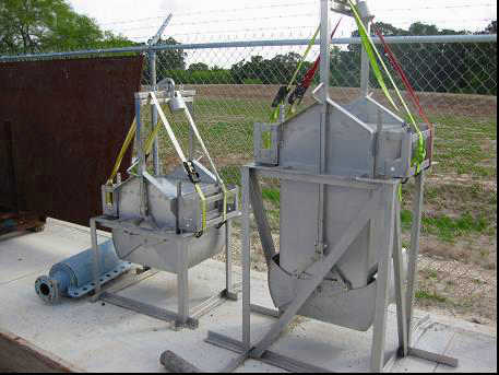
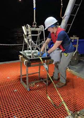
 The TDI-Brooks Auto T-Bar instrument measures the progressive resistance of a soil column to a cylindrical rod (shaped as an upside-down T) as it advances down the soil column at a constant and standard rate of travel. The instrument is shown in Figure 9, with its T-bar protruding below.
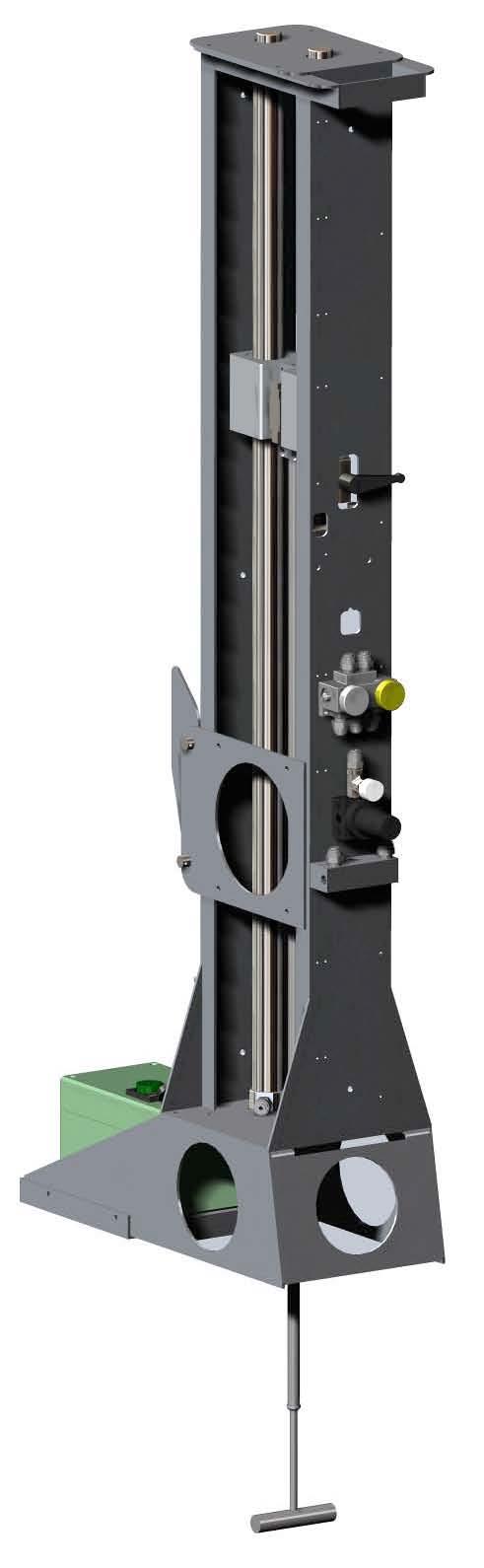 Operation consists of mounting the instrument onto a box corer containing an undisturbed seabed soil sample, connecting the instrument to a shipboard source of compressed air, and starting the automatic advance of the T-Bar into the soil sample. The resistance of the soil is automatically logged during the downward advance until the bottom of the soil sample is reached by the T-bar. The instrument then reverses T-bar movement and logs the soil resistance generated during the upward, retracing return of the T-bar back up to any desired soil depth or to the surface. This sequence of a downward stroke followed by upward re-trace through the failed soil can be continually repeated as many times as desired. Sets of 10 to 30 such cyclic T-bar tests are typical in box cores.
The instrument measures and logs the soil’s resistive force on the T-bar 10 times per second. The T-bar typically auto-advances at 2.0 cm/sec, so a data set is logged every 2 mm of penetration (this standard rate of advance can be changed to address differing client specifications). A single down-stroke test to 100 cm soil depth thus takes 50 seconds with 500 resistive force measurements logged (Table 1). The resistive force is reported in pounds or newtons, and is converted by the processing program into units of pressure (ksf or kPa) by dividing by the cylindrical cross-sectional area of the T-Bar. The standard (medium) T-Bar cylinder diameter is 1.00 in. and its length is 5.00 inches. Smaller T-bars (0.75 in. and 0.50 in. dia.) are also available for quick change-out, each with cylinder length 5 times its diameter. The push rod is sleeved, rendering its frictional drag during advance in either direction to have no measureable component. The calibrated range of the tool is -100 lb (445 N) upstroke to +100 lb downstroke, which translates using an Nt-bar of 10.5 to maximum measureable undrained shear strengths of about 275 psf (13.2 kPa) using the large bar, 500 psf (23.9 kPa) for the medium bar, and 1,100 psf (52.7 kPa) for the small bar. An example of 30 cyclic auto T-bar measurements into a 1m deep box core sample are plotted in the figure below.
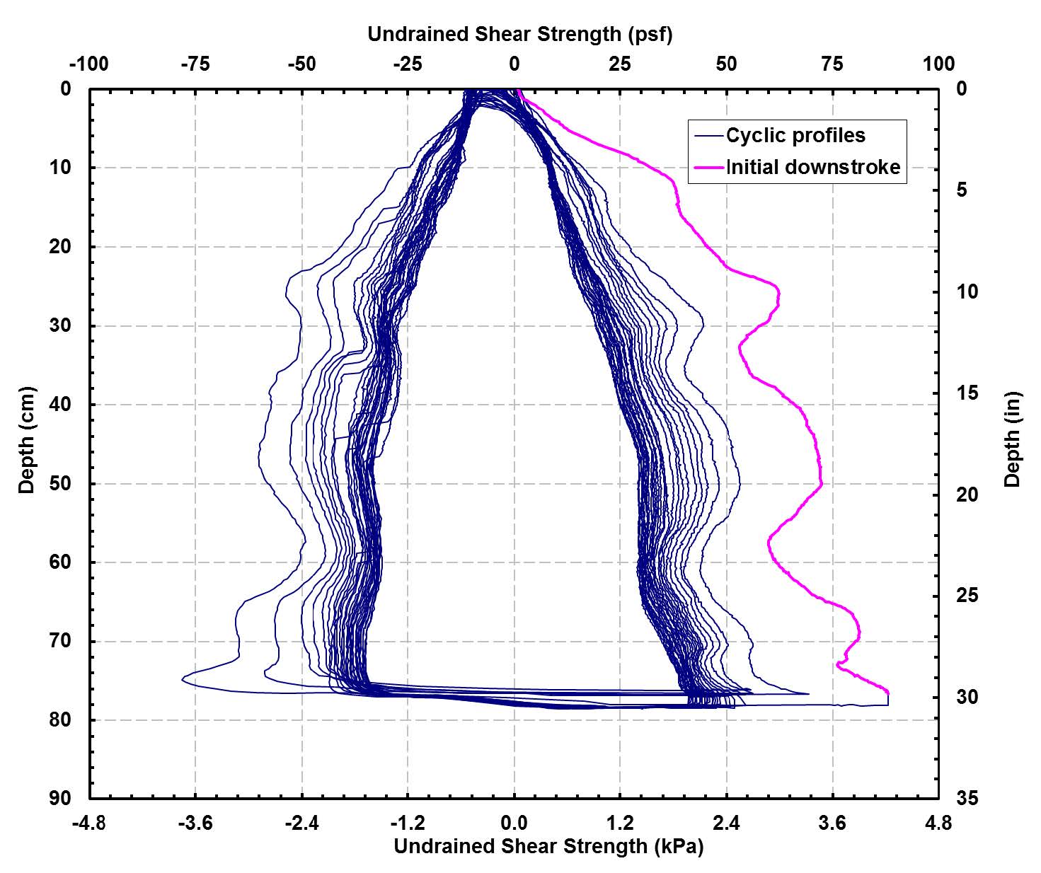
In this figure, the pink trace represents the initial downward stroke of the T-bar into the soil. The two (right and left) nested sets of blue traces are the subsequent progressive upstroke and downstroke data, with the inner traces being the 30th and final stroke set. All measurements have been converted using an Nt-bar of 10.5 to represent undrained shear strength. This plot illustrates the progression of soil reworking toward fully remolded character during the course of the 30 sets of strokes. Such a data set can thus be also used to project fully remolded values at selected soil depths.
Box Coring
Download the Box Core Flyer HERE
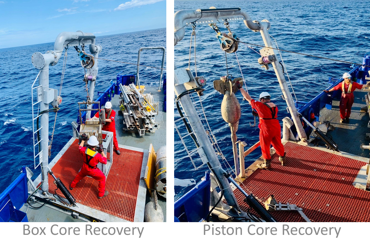
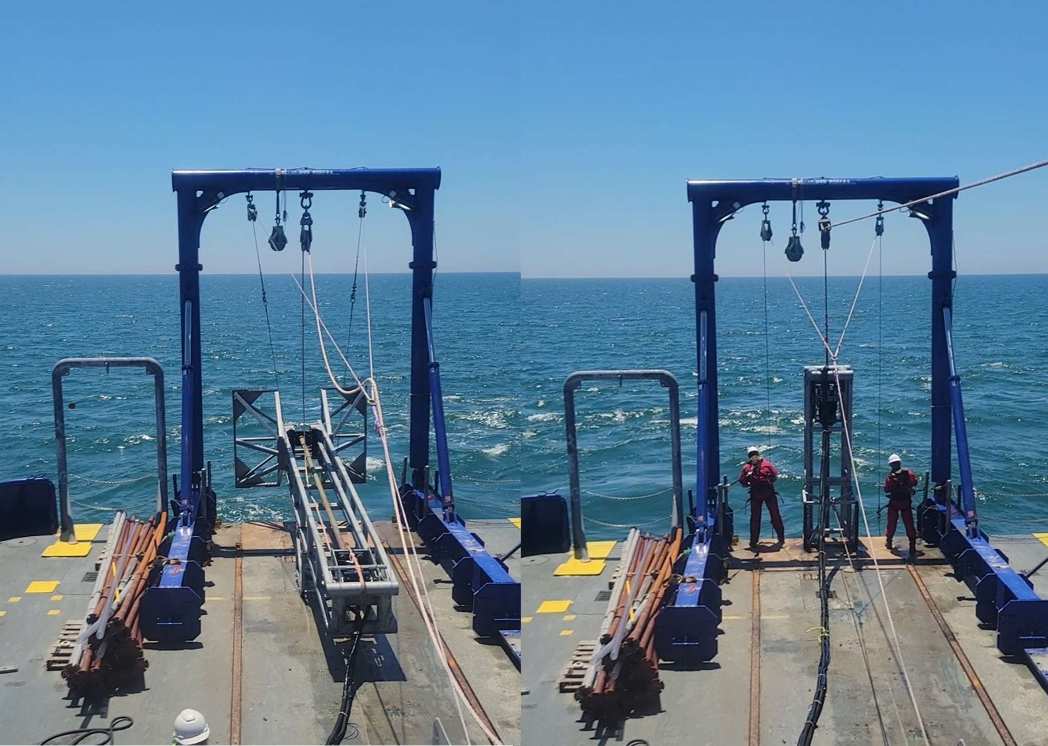
The TDI-Brooks box coring system consists of hardware assemblies designed to be rigged together into a working core rig and deployed to the seabed for extracting a standard cubic box core. Such a core is 100-cm (depth) x 50-cm x50-cm or 50-cm (depth) x 50-cm x50-cm in size. The main winch, main coring rope, and the starboard A-Frame are used for deploying and retrieving the box core rig.
Our box coring system is designed to be a safe, simple, effective mechanism for acquiring large-volume undisturbed shallow sediment samples from the seabed. Such samples are essential for the accurate determination of geotechnical characteristics of marine sediments and the assessment of the benthic ecology (infauna) as required in environmental impact assessments.
The sample box of the core rig is fabricated from stainless steel and is clean and smooth to minimize frictional resistance between the box and the sediment. The corers have a variable weight capability so that the weight stack can be adjusted to suit different seabed conditions that may be encountered.
CPT Stinger
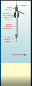
e CPT-Stinger is installed in a JPC core-head, deployed and triggered with the well-proven TDI-Brooks JPC process, and allowed to free-fall ballistically to insert itself into the sediment like a JPC. Once fully embedded in the seafloor with the necessary resulting reaction force now available, the CPT-Stinger is programmed to extend a rod from inside the barrel deeper into the formation (like a stinger) at the standard ASTM (static) cone push rate.
The CPT Stinger can be inserted to about 72 ft BML (while gathering dynamic CPT data), and then used to push a cone penetrometer to about 135 ft BML while gathering static CPT data. Because the extended rod is essentially as long as its barrel, in-situ CPT data can be acquired to sediment depths double of that of the barrel length of the tool (or of a corresponding JPC).’
The CPT Stinger has its own engineered barrel assembly, internal rod set, control module, and PCPT cone with data logger. The rig is deployed in the same manner as if acquiring a JPC. After trigger less than 1 m above the seabed, the dynamic cone data are acquired at a high rate during ballistic penetration into the formation.
After penetration to full embedment, the cone data acquisition continues while the cone is slowly pushed deeper into the formation at a constant rate.
During this push phase, the probe advances at a controlled ASTM rate of 2.0 cm/sec ± 0.5 cm/sec. Data from the probe are logged as the push progresses. Once complete, the system is retrieved to the vessel and data are downloaded from the probe for evaluation and analysis. The tool is then readied for the next deployment, typically in less than 20 minutes, making 3 to 5 deepwater deployments per 12-hour day routine.
The maximum water depth for the CPT Stinger is 3,000 m, but special 4,500 m cones are also available for ultra-deep tests. The tested minimum water depth for the CPT-Stinger is currently 350 m, though a shallower water capability may be possible.
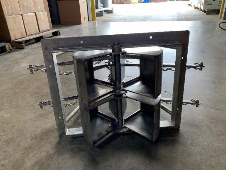
Dual Van Veen Grab Sampler
Download the Dual Van Veen Grab Sampler Flyer HERE
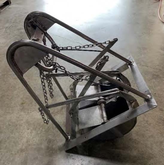
The sampling device is composed of two 0.04-m2 samplers (.08-m2 total) joined together in a single frame. The target penetration depth is 0.1 m, which is the nominal limit of the grab sampler. One sample can be collected for benthic infauna (one side of the grab) and the 2nd side of the grab for geotechnical measurements at each site. A grab sample is deemed successful when the grab unit is > 75% full (with no major slumping). The grab sampler is recovered from the seabed and back onto the vessel at a velocity which minimized any potential loss or disturbance to the seabed sample.

ferritech ft 550 vibrocorer

• High power with up to 75kN thrust
• 1 – 12m modular construction (in 1m increments)
• Rapid mobilisation with plug and play setup
• Change barrels with the frame laid horizontally or vertically
• 2:1 mechanical advantage on lifting wire aiding barrel extraction
• Quick barrel release system
• 300m – 7000m depth rating available
• Stable operation in up to 10 knot currents
• Consumables compatible with Feritech Global gravity and piston corers
• Frame hot dip galvanised to BS EN ISO 1461:2009
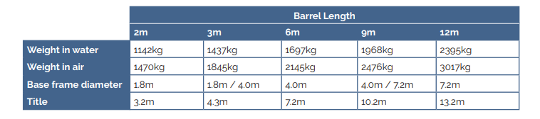
With its modular construction, the entire FT550 system and spares can easily be packed into a
standard 20 foot ISO shipping container.
The FT550 has a proven track record of quickly penetrating consolidated sediments. The variable
frequency has been used time and time again to acquire high quality core samples from stiff clays,
compacted sands, to sites with chalk and gravel.
The magCORE adds the ability to see oncoming ferro-magnetic obstructions within the ground. Thtis has many
uses from UXO (unexploded ordnance) detection to measuring the depth of sheet piling or other metallic
foundations.
The sensors measure in 3 dimensions and so can detect a target both in front of and to the side of the barrel.
The topside controller shows the engineer the information he needs to ensure an efficient, successful and safe deployment and operation. The rugged topscreen unit displaying and logging real time data from the system for the user, including:
• Penetration distance and rate
• Depth sensor
• Inclination
• Settlement into seabed
• Altitude from seabed
• Frequency and power
geotechnical portable 3rd party Tool Kits
TDI-Brooks offers offshore, nearshore, and inland marine geotechnical survey services using a suite of innovative tools for soil sampling and measurement, including box corers (BC), piston corers (PC), gravity corers (GC) and jumbo piston corers (JPC).
We have the following portable geotechnical took kits for use on a 3rd party vessel:
-
Light coring kit: PC, BC operations. Available Winch, Control House, Track, A-frame components additionally.
-
Heavy coring kit: PC, BC, JPC, CPT operations. Available Winch, Control House, Track, A-frame components additionally

Contact us with any questions: info@tdi-bi.com
Gravity CPT (gCPT)
Download the gCPT Flyer HERE
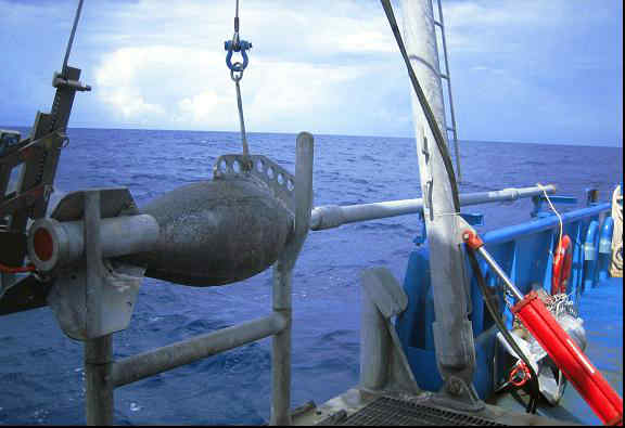
The purpose of the TDI-Brooks Gravity CPT (gCPT) tool is to transport a precisely calibrated memory cone penetrometer down to the seabed/lakebed to gather dynamic PCPT cone data from the mud line to 10+ m BML. In addition to its 1,800 lb (800 kg) driving head with lifting bale and trigger, the rig comprises a self-contained PCPT cone penetrometer that measures tip resistance (qc), sleeve friction (fs),
and pore pressure (u2) using standard ASTM dimensions and protocols for its 15-cm2 cone.
Once the cone insertion into the soil is complete (within 5 sec after trigger), the tool’s precise location is recorded (using USBL when in deepwater), and then the tool is retracted from the soil and retrieved to the deck. Cone data are immediately downloaded from the probe for evaluation and analysis. The tool is readied for the next deployment, typically in less than 5 minutes, making numerous measurements per day feasible, depending only on water depth and winch speed. The maximum water depth for the gCPT system is 3,000 m, but special 4,500 m cones are also available for ultra-deep tests. High quality in situ dynamic PCPT data can be rapidly acquired from the mudline to 30+ft (9+m) below the mud line in a safe, rapid, and cost-effective manner. Probe data are logged 200 times per second. This logging rate allows the cone parameters to be measured at sediment intervals no larger than 2-5 cm even at ballistic advance velocities reaching up to 10+ m/sec.
Parameters logged include tip resistance (mPa), sleeve friction (kPa), pore pressure (mPa), cone acceleration (m/sec2) and cone tilt (°) from vertical. We calibrate and adjust these dynamic cone data to static PCPT data-equivalent using our proven and calibrated database of cone rate effect measurements with soil type. Adjustments due to the advance rate effect are slight for tip resistance and sleeve friction, and negligible for pore pressure. Comparisons between side-by-side static PCPT data (2 cm/sec ASTM-rate cone advance) with the rate adjusted dynamic PCPT data acquired during the tool’s insertion have been remarkably good for more than 400 sites in our international database.
More info on Gravity CPT rev6 HERE
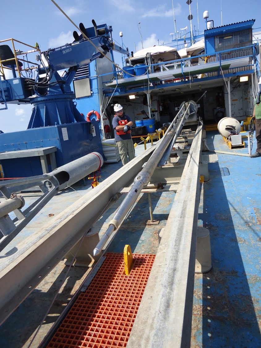
Jumbo Piston Coring
 The TDI-Brooks jumbo piston coring (JPC) system consists of various hardware assemblies designed to be fastened together into a working core rig and deployed to the seabed for extracting a “jumbo” piston core. The deployed core rig comprises assemblies for the core head, the core barrel, the piston, and the trigger system. The JPC rig can be assembled to collect a sample up to 64 feet long. There is also lifting assembly that attaches to the trigger system, allowing the system to be deployed with an A-frame. The core barrel assembly is made up of selected sections of core barrel, connecting collars, a core liner assembly inside the barrel assembly, a core catcher, a core cutter, and set screws to hold the barrel assembly together. The inner diameter of the core liner is 4 inches. The barrel length can be adjusted in 5-foot and 10-foot increments by adding barrel sections and connecting collars. The trigger assembly is made up of the trigger arm, pendant clamp, trigger weight, trigger wire, and trigger wire connecting system. The assembled core rig weighs between 5,500 and 7,000 lbs, depending on the length of core to be acquired. The weight of the core head is adjusted by adding weight as lead ingots to a starting weight of about 5,000 lb.
The main winch, main-line rope, and the stern A-Frame are used for deploying and retrieving the JPC rig. In addition to the deployed hardware, several assemblies are mounted to the vessel working deck to manage the deployment and retrieval of the coring rig. These assemblies include the main sheave from the stern A-Frame and the deployment, retrieval and trigger tugger winches with their hydraulic power pack.
Manta-200 CPT System
Download the Manta-200 CPT Flyer HERE
The TDI-Brooks’ Manta-200 Cone Penetration Testing (CPT) system is suitable for almost any project in shallow water up to 150 meters. The CPT system is powered by a unique Continuous Drive System (CDS) that was designed with a clear focus on durability and high production. It also guarantees uninterrupted penetration of the cone.
The Manta-200 CPT system is a modular design capable of delivering results on even the most challenging of projects with a chain-drive based system that can reach penetration depths of up to eighty meters. Both casings and tubes can be operated simultaneously.
During CPT operation the Manta is controlled from the surface with a real time link over a combined power and communication umbilical. Data can be viewed in real time allowing operators to manage the push and react to local sediment conditions to provide the highest quality data to the greatest depths possible.

The Manta system is composed of the base equipment which is then completed with supporting options like ballasts and winches all depending on your project’s requirement. The heart of each system is its capability of retrieving and processing high quality data. During CPT operation the Manta is controlled from the surface with the control box. The controls are intuitive and easy to use. Data is viewed in real time as with a conventional CPT. Data, communication and power are all handled by the umbilical.
The Manta-200 measures 2,200 x 2,200 x 2,300 mm(L x W x H) when being transported. The basic setup is transportable in 20 ft sea containers.
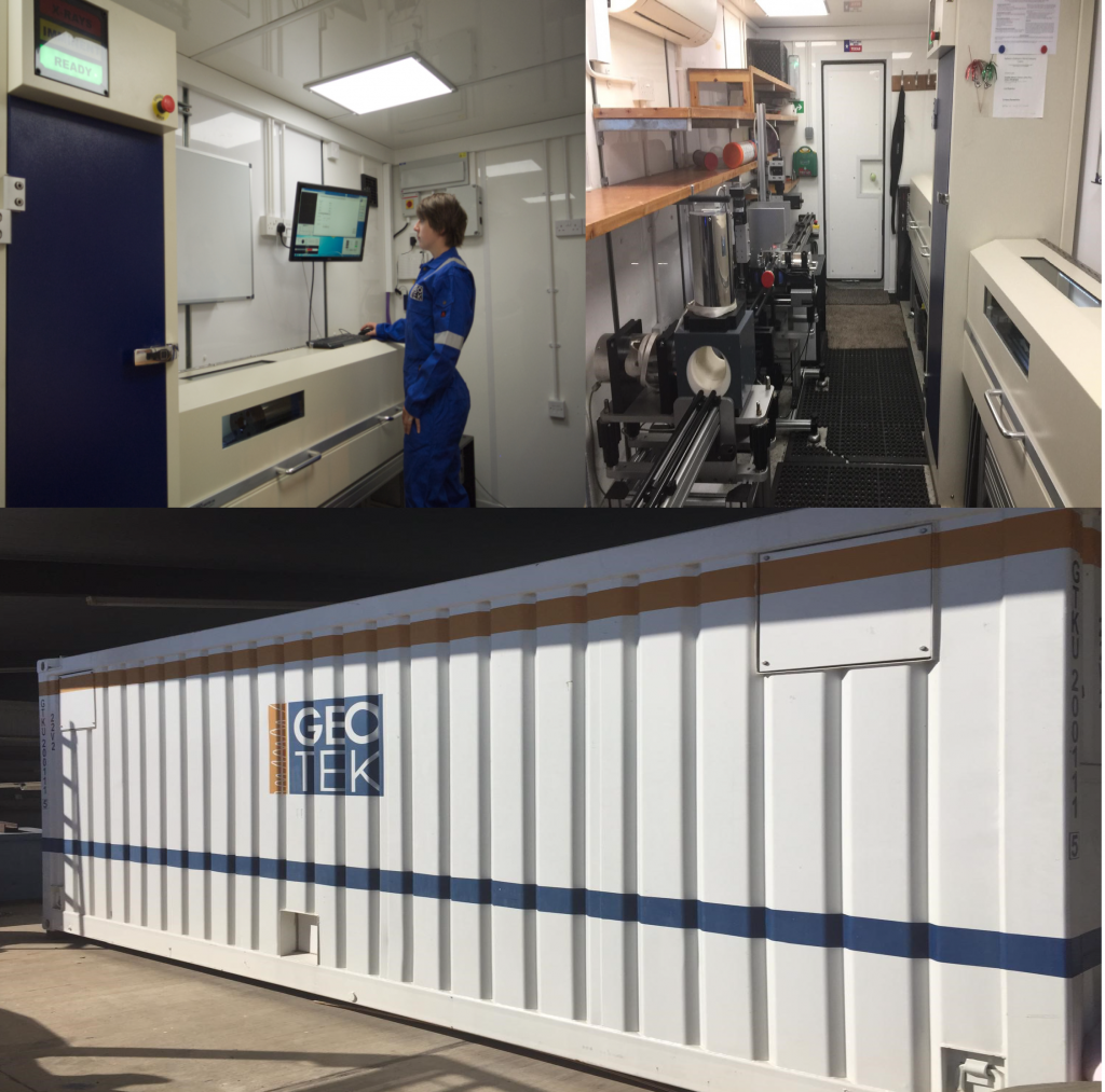
MULTI-SENSOR CORE LOGGING (MSCL)
MSCL systems rapidly and non-destructively obtain high-resolution (typically 1 cm to 10 cm downcore spacing) geophysical and geochemical data from sediment and rock cores. The high quality multi-parameter stratigraphy delivered from MSCL systems enables facies classification and soil/rock typing ahead of, or in support of a visual description. Ultimately this leads to improved laboratory test planning for any necessary destructive or advanced laboratory testing. The Geotek core logging services team follows strict calibration procedures for each core size and liner type to ensure consistency and accuracy of data collection.
Sediment or rock cores with or without metal or plastic liners up to 1.5 m long and 155 mm in diameter can be accepted. Physical, elemental and mineralogical properties can be obtained from whole or split/slabbed core samples regardless of whether they are within a liner or not. An MSCL dataset provides vital information about core heterogeneity or homogeneity ahead of destructive laboratory testing or visual logging.
More details here: TDI-Brooks Partners With Geotek UK to Deliver Expanded Services – TDI-Brooks International (tdi-bi.com)
neptune 5,000 Coil Rod CPT System
| 5cm ² Detachable Cone, 10cm² Cone and T-Bar Cone | |
| 35kN Push Capability | |
| Up to 20m Penetration from Coiled Rod | |
| Easily Deployed Compact Sub-Sea Frame | |
| Real Time Control and Display | |
| Single Coax Connection for Power and Data | |
| Automatic Safety Cut-Outs | |
| Low Maintenance, Low Consumable Use | |
| Easy to Operate Windows™ based PC Control |
This highly advanced equipment is designed for thrusting 5 cm² or 10 cm² Digital Cones. The unit can thrust up to a maximum of 70 MPa and has a depth rating of 3000 meters. This is an excellent tool for investigating seabed conditions prior to seabed installations such as pipelines, power cables and underwater constructions. The measurements comprise of penetration depths, cone resistance, sleeve friction, pore pressure and inclination from vertical.
The system can be mobilised to a variety of vessels depending upon the nature of the project, ranging from the fuel efficient vessels at 30m LOA, to regular charter vessels upwards of 50-70m LOA. The high mobility and small footprint of 2.2m x 2.2m makes it perfect to be mobilised onboard vessels of opportunity.
The 5000 is fitted with 5cm or 10cm Digital Piezocones and benefits from self-tuning telemetry. The surface controls unit operates a Microsoft Windows PC combined with the established Neptune software package, providing real-time data.

neptune 3,000 Minature Coiled Rod CPT System
The TDI-Brooks Datem Neptune 3000 Miniature Coiled Rod CPT System is a coiled rod Cone Penetration Test System featuring a 10kN Push capability. This lightweight coiled rod CPT system is for use in up to 3000 Meters of water and designed to withstand the harshest of sea environments.
A coiled tubing CPT system that is easy to mobilize, featured coiled rod system enables the Neptune 3000 to be self-contained and compact, therefore allowing the system to be deployed from the smallest of survey vessels where space is often of a premium. This CPT unit is commonly used for pipeline surveys for oil and gas operators and cable route surveys for offshore renewables.
- 2cm ² Detachable Cone, 5cm² Detachable Cone and T-Bar Detachable Cone
- 10kN Push Capability
- Up to 10m Penetration from Coiled Rod
- Compact and Easily Deployed Sub-Sea Frame
- Real Time Control and Display
- Single Coax Connection for Power and Data
- Automatic Safety Cut-Outs
- Low Maintenance, Low Consumable Use
- Data Comparable to 10cm² Systems
- Easy to Operate Windows™ based PC Control
The Neptune 3000 CPT enables its operators to perform an in-situ real-time test of the subsea soil structure therefore eliminating/reducing the requirement for time intensive soil sample extraction, storage and examination, thus reducing project duration and therefore cost.
The system uses Datem’s digital 2cm cones, 5cm cones and T-Bar cones to suit all subsea soil conditions, providing axial load, sleeve friction, pore pressure, dual axis tilt and temperature data in real time (selectable up to 20hz) as they penetrate through the soil with data comparable to that of 10cm cones. With a push force of up to 10kN and a maximum push distance of 10Mtrs the Neptune 3000 is an industry renowned and hugely popular CPT system globally.

Piston Coring
Download the Piston Corer Flyer HERE
The TDI-Brooks 3-inch-diameter (3-in.) piston coring system consists of various hardware assemblies designed to be fastened together into a working core rig and deployed to the seabed for extracting a piston core. The PC rig can be assembled to collect samples up to 30 feet long and collects a 3 inches diameter sample. The deployed core rig comprises assemblies for the core head, the core barrel, the piston, and the trigger system. The core head assembly is made up of a lead-weighted core head with nosepiece and a coupling with which to attach lengths of core barrel sections. It also has a lifting flange assembly that attaches to the trigger system. The trigger assembly is made up of the trigger arm, pendant clamp, trigger weight, trigger wire, and trigger wire connecting system. The core barrel assembly is made up of selected lengths of core barrel sections, connecting collars, a core liner inside the barrel assembly, a core catcher, a core cutter, and set screws to hold the barrel assembly together. The barrel length can be adjusted in 5-foot increments by adding 5 or 10-ft barrel sections and connecting collars.
The main winch, main-line coring rope, and the starboard A-Frame are used for deploying and retrieving the 3-in. piston core rig. In addition to the deployed hardware, several assemblies are mounted to the vessel working deck to manage the deployment and retrieval of the coring rig. These assemblies include the main sheave from the starboard A-Frame and the core-head and trigger tugger winches with their hydraulic power pack.
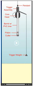
A piston corer uses a free fall of the coring rig to achieve the desired initial force on impact, and a sliding piston inside the core barrel to reduce inside wall friction with the sediment and to assist in the rapid evacuation of displaced water from the top of the corer. These elements act in concert to maximize core recovery.

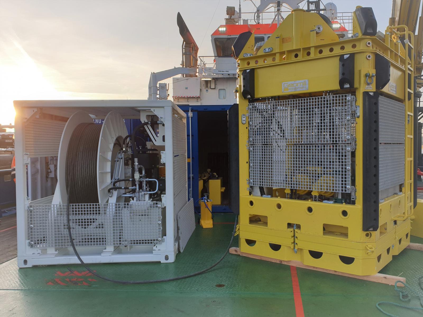
tdi-brooks pneumatic vibrocorer
Vibracoring is a technique for collecting core samples of seabed sediments and wetland soils. The core barrel is incrementally driven into sediment aided by gravity, using an asymmetric pulsing energy imparted to the barrel from the vibrating head. These pulses are generated by a pneumatic pressure drop across the head, which produces mechanical pulses (hammer blows) in the downward direction at a 10-20 Hz rate. The pulses cause a thin layer of material to mobilize along the outer barrel wall and the inner core liner wall, reducing friction, easing penetration into the substrate, and aiding recovery of the soil material into the liner.
The subsea equipment is built to withstand the harsh offshore environment and unforgiving handling. It is designed for safe deployments and retrievals using a robust process from the stern of the vessel. Operations are safely conducted by a winchman, an a-frame operator, and two deckmen. Due to its simple-to-assemble modular construction, the system can be mobilized very quickly for cores of 1-6-m.
• Vibrator Type: Pneumatic impacting piston vibrator
• Air Consumption: 250CFM @120psi
• Frequency: 600-1200 bpm
• Waveform: asymmetric Impacting
• Tool Dimensions in standard 6m configuration: 292″ Tall x 82″ x 105″
• Tool Weight in air:4,600lb
• Tool Weight in water: 3,900lb
• Stroke in standard 6m configuration: 5.75m
• Liner ID: 2.75″
• Cone Barrel ID: 3.0″
• Cone Barrel Wall: 1/8″
• Penetration Measurement: 5cm resolution, real time display at winch
• Water Depth Rating: 75m
• Maximum Core Length: 5.75m
• Lifting frame: 15,000lb crane/winch and a- frame
• Power requirement: 440V ø3 300KVA start / 100KVA run
XCT: Standard X-Ray CT System
TDI-Brooks has a Geotek XCT system on campus to acquire both 2D X-ray transmission images and 3D X-ray CT volumes from lined whole core, split core, or slabbed core sections. Automated rotation of lined core sections allows users to visualise and record three-dimensional structures within the cores. These rotational images are used for computed tomographic (CT) reconstructions. X-ray CT imaging provides valuable quantitative data as well as information about core quality for sub-sampling or further analyses. More details here: TDI-Brooks Partners With Geotek UK to Deliver Expanded Services – TDI-Brooks International (tdi-bi.com)

Geotechnical Laboratory Analysis and Interpretation
TDI-Brooks offers a comprehensive suite of geotechnical analytical services for characterizing offshore geotechnical samples. In addition to our offshore geotechnical sampling toolkit, TDI-Brooks can provide soil testing services through our in-house geotechnical laboratory.
We possess a USDA permit for the importing of foreign soils for laboratory analysis.
GEOTECHNICAL LABORATORY INFO HERE
seabed Geochemical “Seep-Hunting”
Seabed Geochemical Seep Hunting SURVEYS
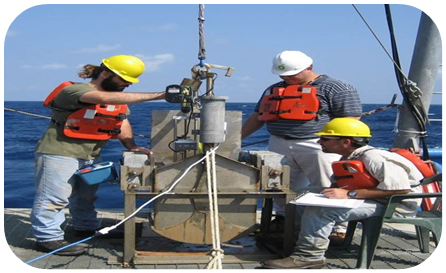
The TDI-Brooks team features experts in conducting offshore Seabed Geochemical “Seep Hunting” Exploration and Heat Flow programs for the world’s leading petroleum producers. TDI-Brooks and our partners have been involved for 40 years in the design and execution of numerous global ‘seep hunting’ MBES programs. Geochemical Seep-hunting campaigns reduce offshore exploration risk and cost.
TDI-Brooks uses a sequence of specific procedures that we developed and improved over several decades. Our method consistently yields highly accurate identifcation and a quantitative evaluation of potential sites with migrated oil. Preparation for your project begins with a thorough assessment of legacy seismic and other available geological data.
Deep seismic and multibeam surveys are used to select piston coring locations based on surface expression of deep faults and other features related to conduits for upward migration of hydrocarbons.
Since 1996, TDI-Brooks has collected over 50,000 deep water piston core sediment samples and heat flow stations for every major oil company, in areas such as the Caribbean, the Gulf of Mexico (USA and Mexico), the Mediterranean, the North Atlantic, and offshore Brazil and West Africa.
SGE MBES Global Coverage – 224,350 square kilometers
| 8,000 sq km | 2010 RIL ‘Borojo’ North / South Colombia SGE/HF program |
~8,000 sq km, collected with EM710 | RV GeoExplorer |
| 3,350sq km | 2011 ExxonMobil Vietnam Blocks 156-159 SGE/HF program | ~3,350 sq km, collected with pole mounted Reson 8160 | RV Rylan T |
| 5,000 sq km | 2015 Tullow Jamaica SGE/HF | ~5,000 sq km, collected with EM710 | RV GeoExplorer |
| 10,000 sq km | 2017 Kosmos Morocco SGE/HF | ~10,000 sk km, collected with EM710 | RV GeoExplorer |
| 115,000 sq km | 2018 TGS MSGBC West Africa SGE-HF program | ~115,000 sq km, collected with EM302 | RV Gyre |
| 83,000 sq km | 2019 TGS Nigeria Seep Program | ~83,000 sq km, collected with EM302 | RV Gyre |
Our interpretation of survey results is made even more robust by comparison with our world-wide database of SGE survey results from 100,000+ samples we have collected, analyzed, and interpreted over the years. We add our knowledge of historical background levels of the analytes for an area, environmental factors, and any unique characteristics of the region being sampled. The process consists of the following sequential steps: Core Site Selection, Core Acquisition, Laboratory Analysis, and Interpretation.
Deep seismic and multibeam surveys are used to select piston coring locations based on surface expression of deep faults and other features related to conduits for upward migration of hydrocarbons.
Download the Surface Geochemical Seep Hunting flyer HERE
Surface Geochemical Exploration is a petroleum prospecting tool based on the premise that traces of upward migrated petroleum from deep source rocks and reservoirs can be detected in selected seabed sediments and used to evaluate exploration potential.
Geochemical Posters
- Characterization and source identification of gas bubbles observed at Mississippi Canyon Block 20 (MC20) in the Gulf of Mexico, Michael Gaskins, Dr. Bernie Bernard, Dr. James Brooks, J18324 NOAA MC20 GOMOSES Poster Rev0
- Models of Natural Gas Origin – A Short History, Dr. Bernie Bernard, Bernard Hedberg Poster
Contact us with any questions: info@tdi-bi.com
Multibeam Core Site Selection
Historically the design of SGE programs has relied on the use of regional 2D and 3D seismic data for the identification of potential surface seepage targets for core sample acquisition. While this technique has produced good results, seismic data has a number of drawbacks:
- High cost and operational complexity of acquisition;
- Limited areal coverage of the area of interest; and
- Low resolution.
In the past decade, there has been an increased use of multibeam bathymetric survey data (bathymetry, backscatter and water column plume) as a cost effective alternative / complimentary tool for the identification of seepage targets for SGE core sampling. Compared to 2D or 3D seismic, multibeam surveys have a number of advantages including:
- Lower cost and operational complexity of acquisition;
- 100% areal coverage of the area of interest;
- Very high resolution;
- Low probability of negative impact on marine mammals, environmental permitting issues reduced;
- Rapid turnaround time of data processing and interp / seep target selection;
- Can be used independently or in conjunction with 2D or 3D seismic data for seep target selection ; and
- Seeps can have a bathymetric or backscatter signature on the seafloor or water column, or both.
TDI-Brooks and our partners have been involved in the design and execution of numerous ‘seep hunting’ MBES programs. TDI-Brooks operates two vessels with Kongsberg MBES systems, the R/V Gyre and R/V Proteus, and has chartered third party vessels equipped with similar MBES systems suitable for seep hunting missions.
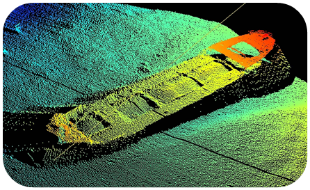
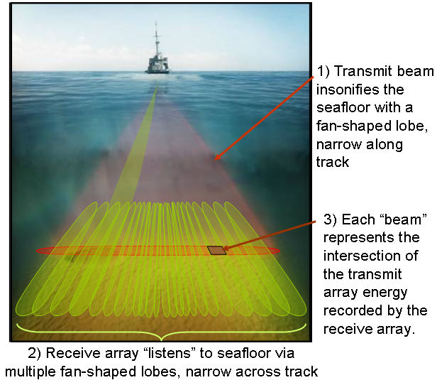
Multibeam echo sounders, like other sonar systems, emit sound waves in the shape of a fan from directly beneath a ship’s hull. These systems measure and record the time it takes for the acoustic signal to travel from the transmitter (transducer) to the seafloor (or object) and back to the receiver. In this way, multibeam sonars produce a “swath” of soundings (i.e., depths) for broad coverage of a survey area. Survey speed is typically higher than seismic operations (up to 10 kts).
|
Above image courtesy of ONE, LLC. |
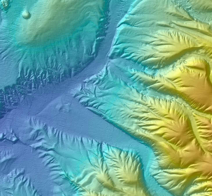 |
| MBES operation and example of processed bathymetry data from EM710 on RV GeoExplorer | |
The area of coverage on the seafloor (swath) per ping depends on the depth of the water, seafloor composition, and the operating frequency of the multibeam sonar. Echosounders that transmit low frequency sound can travel a longer distance in the water (increased range and coverage) but have a lower resolution and are less precise. Sound from high-frequency echosounders cannot travel long distances in water but achieve a higher resolution and are more precise.
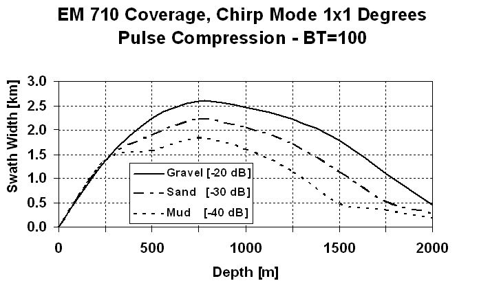
Expected range and coverage of a Kongsberg EM 710 MBES operating @ 70 – 100 kHz

Expected range and coverage of a Kongsberg EM 302 MBES operating @ 30 kHz
Most mid to deep water MBES systems are capable of meeting the resolution / data quality requirements for seep hunting missions. In general, lower frequency MBES systems will allow for increased coverage and reduce survey time, but this may be offset by higher vessel costs, as these system typically require a larger vessel to mount the transducer arrays than higher frequency systems (which use smaller transducer arrays).
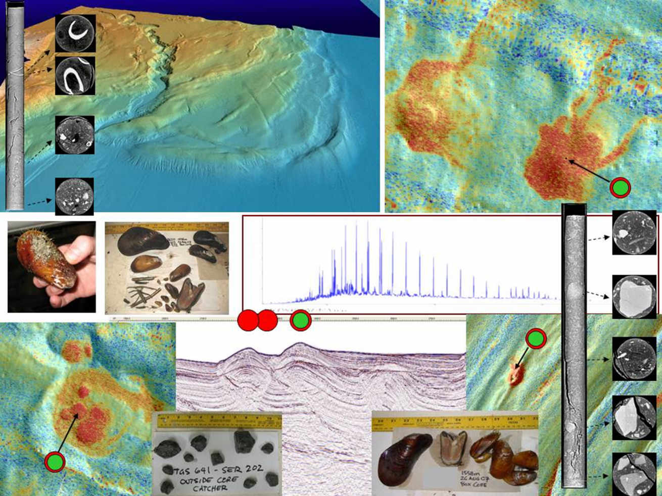
Hydrocarbon Seep Identification with MBES data
The typical multibeam dataset for seep identification will consist of:
- Bathymetric surface grid (5 – 20m resolution)
- Quantitative backscatter grid (3 – 5m resolution)
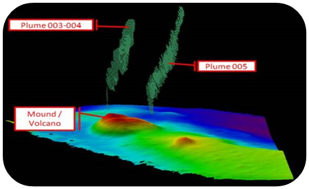
- Water column plume data
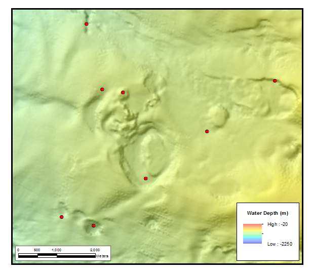
Bathymetry grid showing typical expulsion features (mounds and pockmarks).
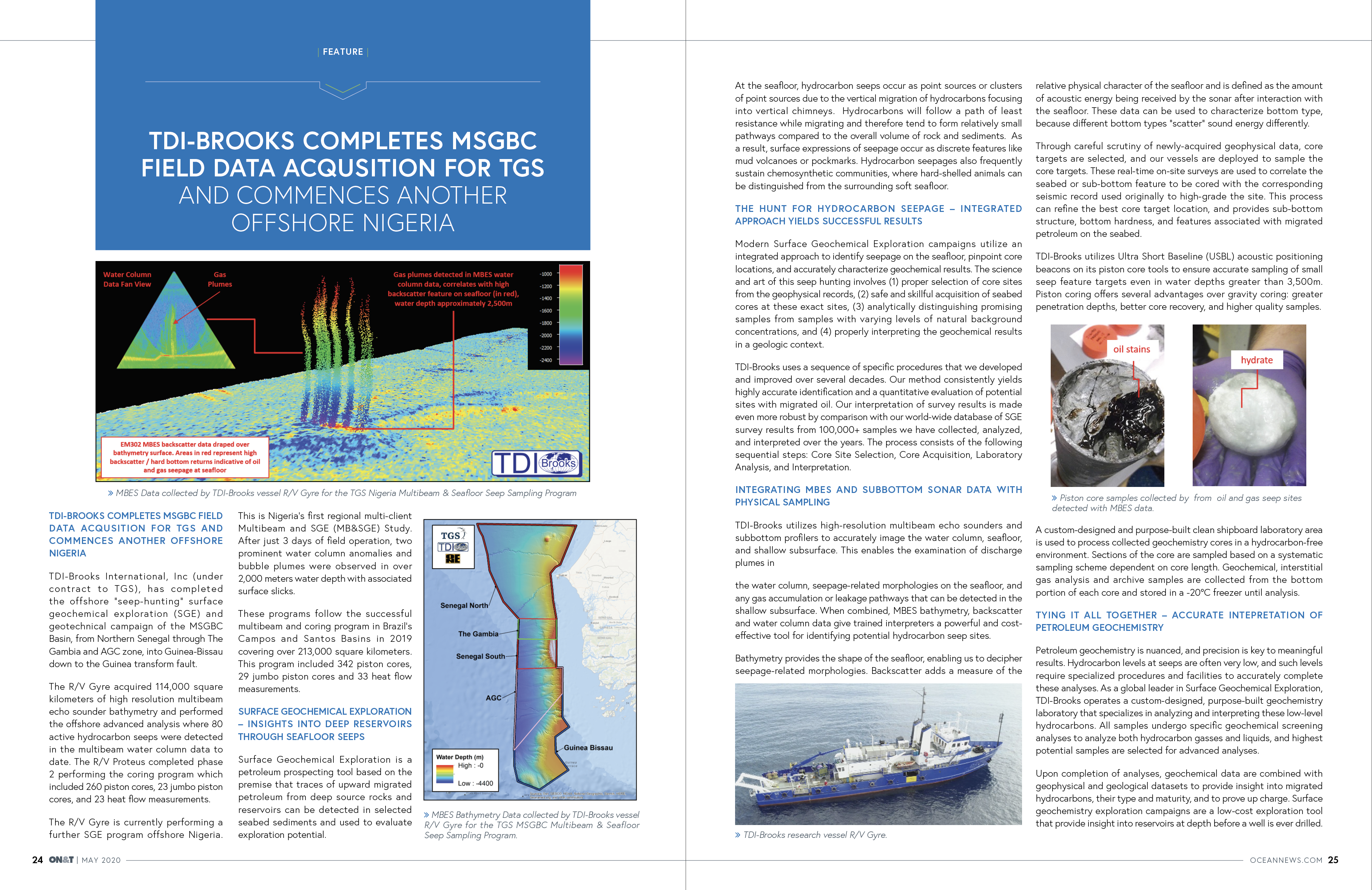
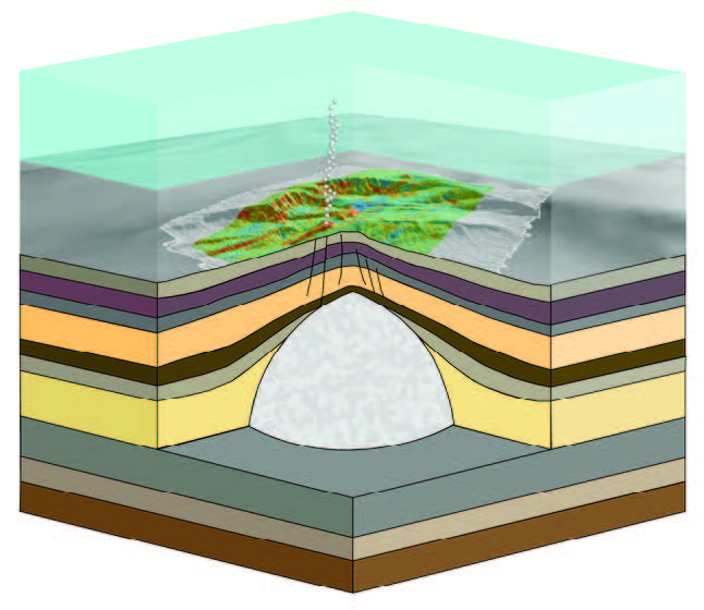
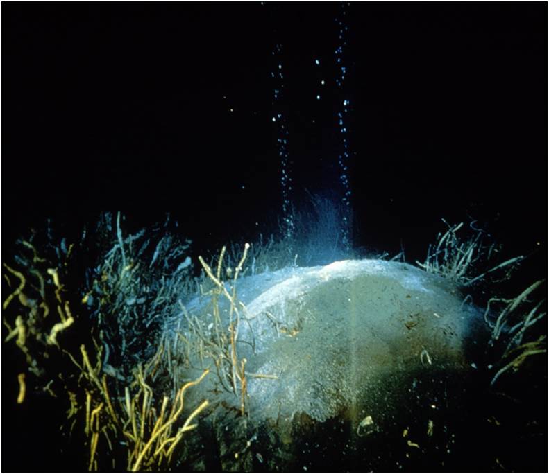
Hydrocarbon seeps occur as point sources or clusters of point sources due to the vertical migration of hydrocarbons focusing into vertical chimneys. Hydrocarbons will follow a path of least resistance while migrating and therefore tend to form relatively small pathways compared to the overall volume of rock and sediments. As a result, surface expressions of seepage occur as discrete features, often with bathymetric character, such as a mud volcano or pockmark.
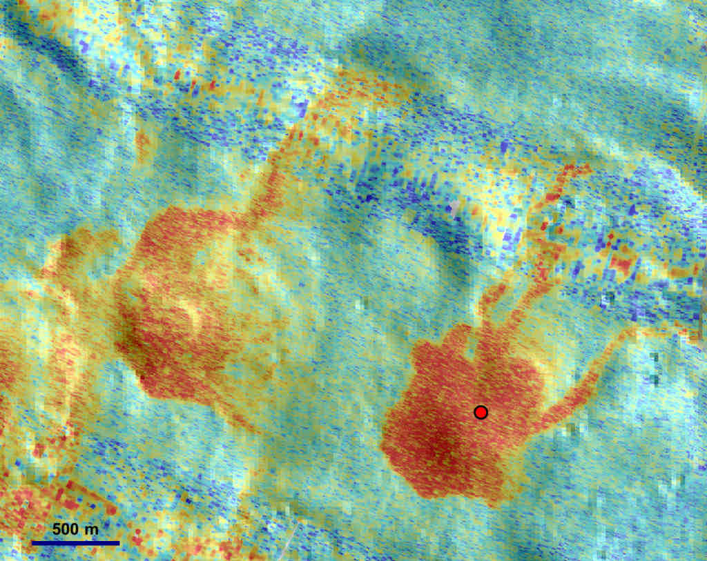
Multibeam backscatter grid draped over bathymetry surface, high backscatter values in red.
Backscatter is defined as the amount of acoustic energy being received by the sonar after interaction with the seafloor. This data can be used to characterize bottom type, because different bottom types “scatter” sound energy differently. For example, a softer or smoother bottom such as mud will return a weaker signal than a harder or rougher bottom, like rock.
While some surface seeps have an easily identifiable surface expression, there are many more occurrences with either very subdued or absent bathymetric response. Hydrocarbon seepage provides nutrients to chemosynthetic fauna, and also leads to precipitates such as authigenic carbonate, and, in appropriate temperature and pressure conditions, seafloor or near-seafloor gas hydrate. All of these conditions have an impact on the acoustic properties of the seafloor or the shallow sub-surface and can be identified by an elevated backscatter response. This backscatter response is the reason seep hunting works so well in the marine environment.
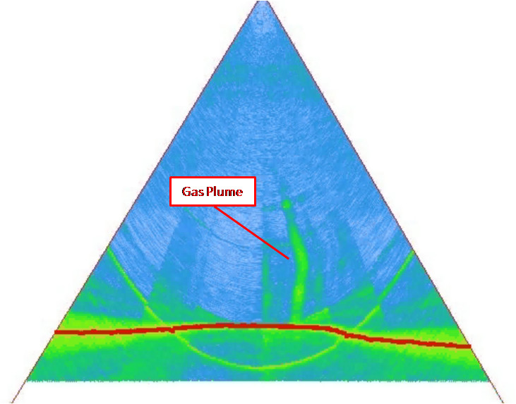
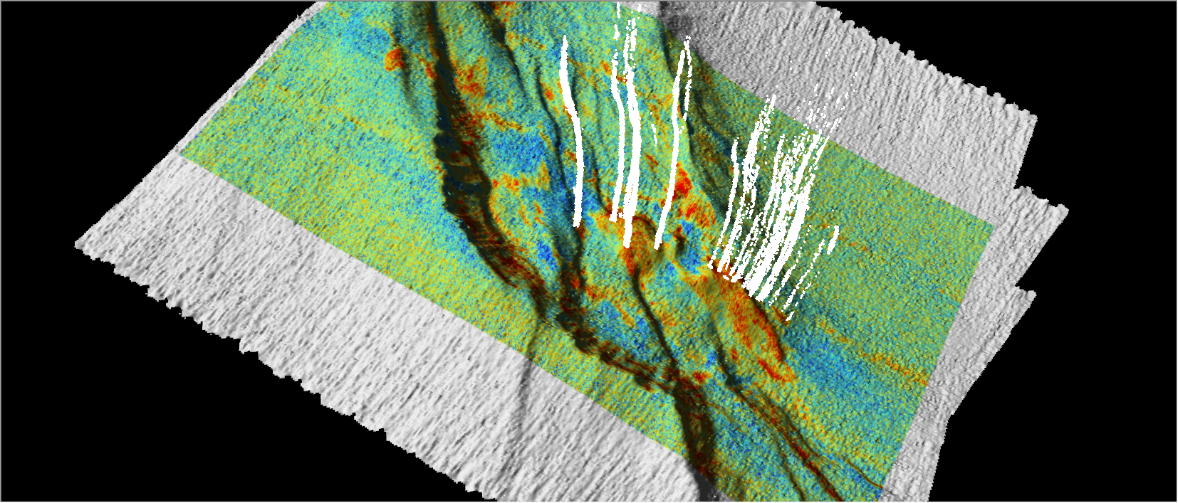
Gas plume detected in MBES water column data
In addition to recording the bottom return data (in the form of bathymetry and backscatter), many modern generation MBES systems can record the returns throughout the entire water column. These data can be used to detect bubbles or gas plumes above the seafloor, which could be indicative of hydrocarbon seepage. These plume data can be digitized and georeferenced to correlate with bathymetry and backscatter data.
When combined, MBES bathymetry, backscatter and water column data give trained interpreters a powerful and cost effective tool for identifying potential hydrocarbon seep sites.
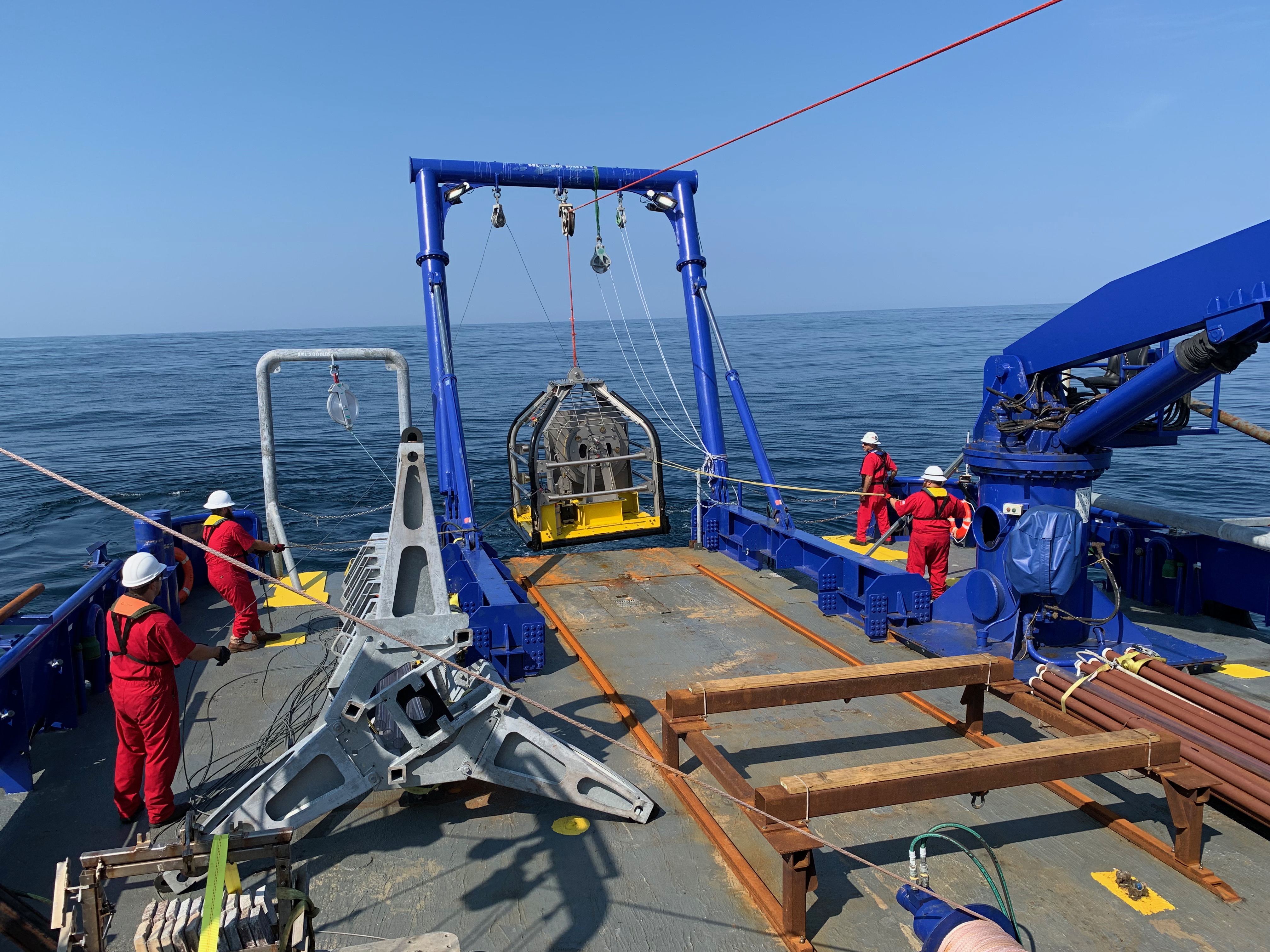
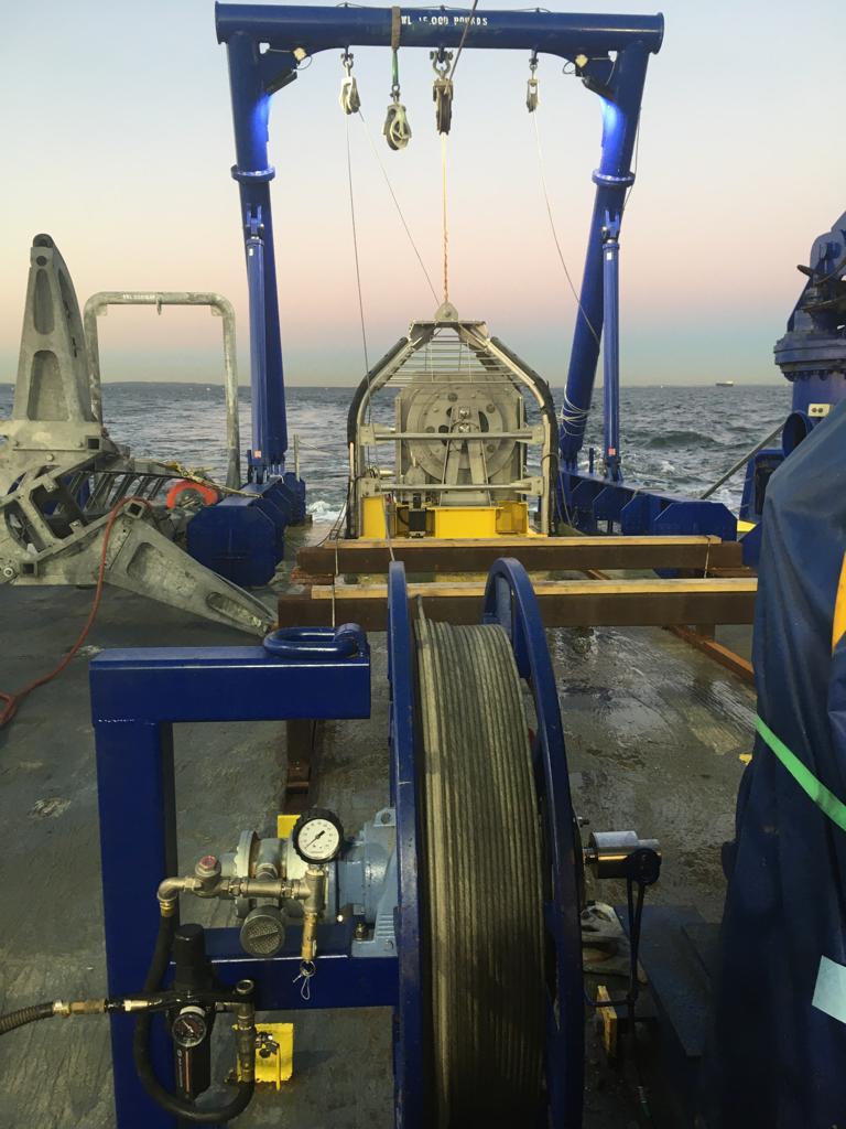
Piston Core Acquisition
Our vessels deployed to sample the core targets typically collect additional acoustic data with a hull-mounted sub-bottom profiler prior to core acquisition. These real-time on-site surveys are used to correlate the seabed or sub-bottom feature to be cored with the corresponding seismic record used originally to high-grade the site. This process can refine the best core target location, and provides sub-bottom structure, bottom hardness, and features associated with migrated petroleum on the seabed.
We use USBL navigated piston coring to collect the precisely located sediment core samples. Piston coring offers several advantages over gravity coring: greater penetration depths, better core recovery, and higher quality samples.
Geotechnical Coring with Stinger Video HERE
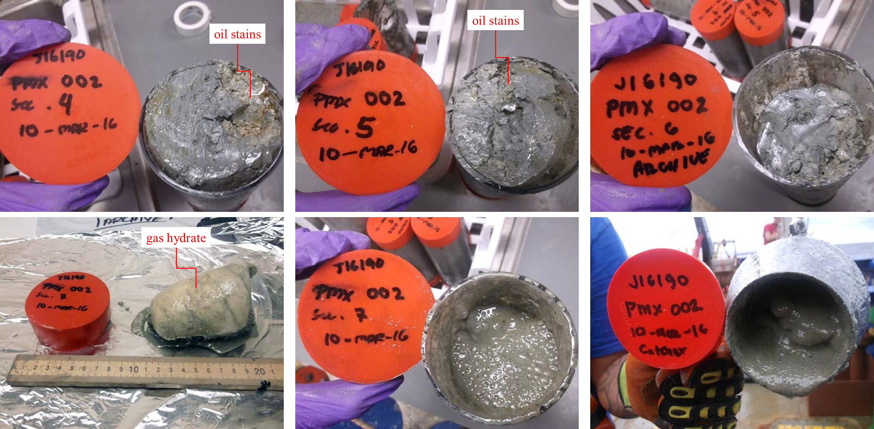
Using piston coring to sample depths up to 6 meters significantly reduces intracore variability due to bioturbation, loss by diffusion of gases, and mixing of natural hydrocarbon seepage or pollution in the top meter of sea floor sediments with deeper sections of the core. In particular, the quality of information gained from measurement of sediment gases increases dramatically in sections collected deeper than about 2.5 meters. Sediment gas concentrations can change several orders of magnitude through the 2 to 5 meter depth range in marine sediments, greatly enhancing the type and quality of measurements that can be made on the samples.
Geotechnical Coring Operations Video HERE
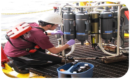
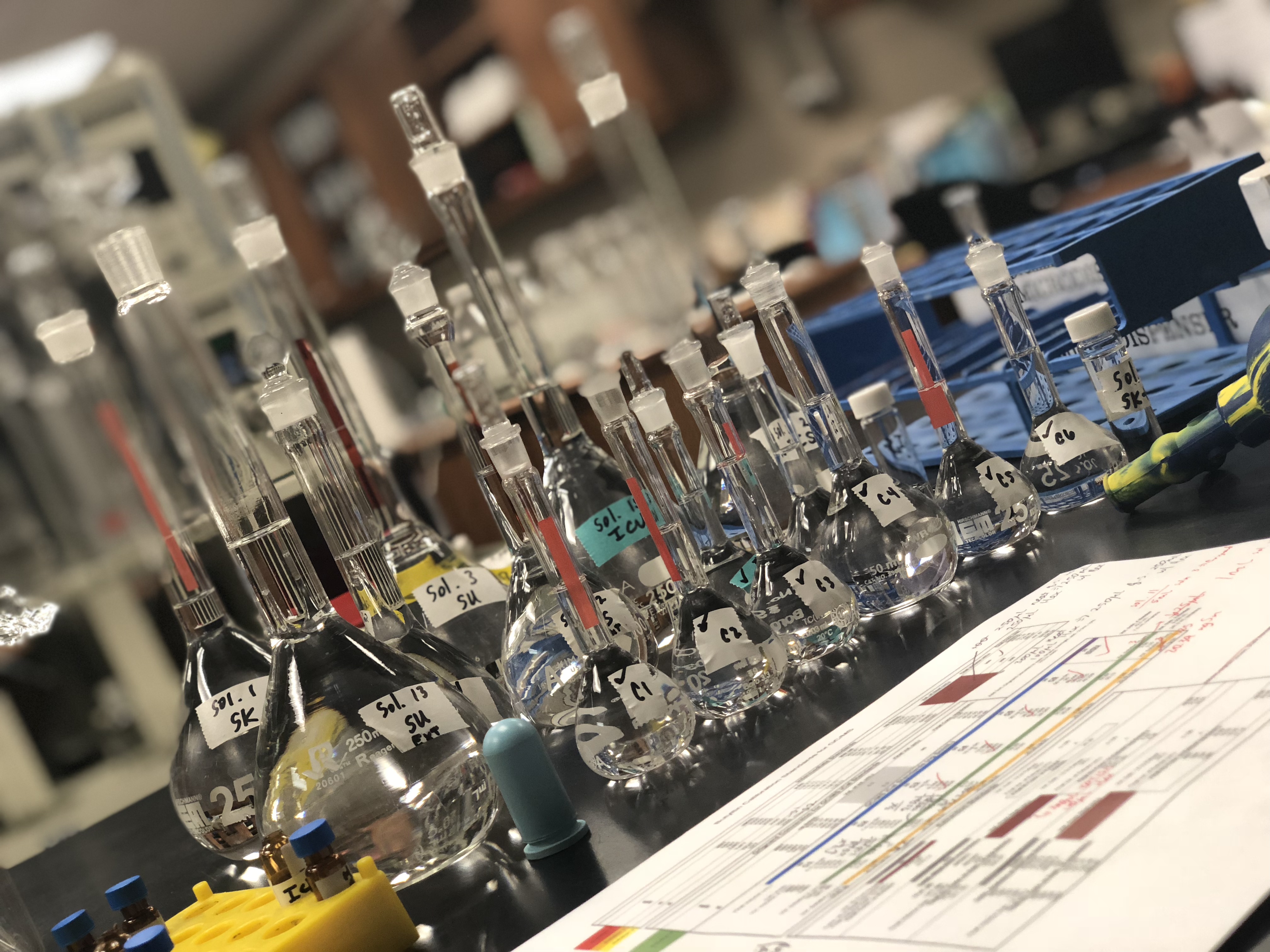
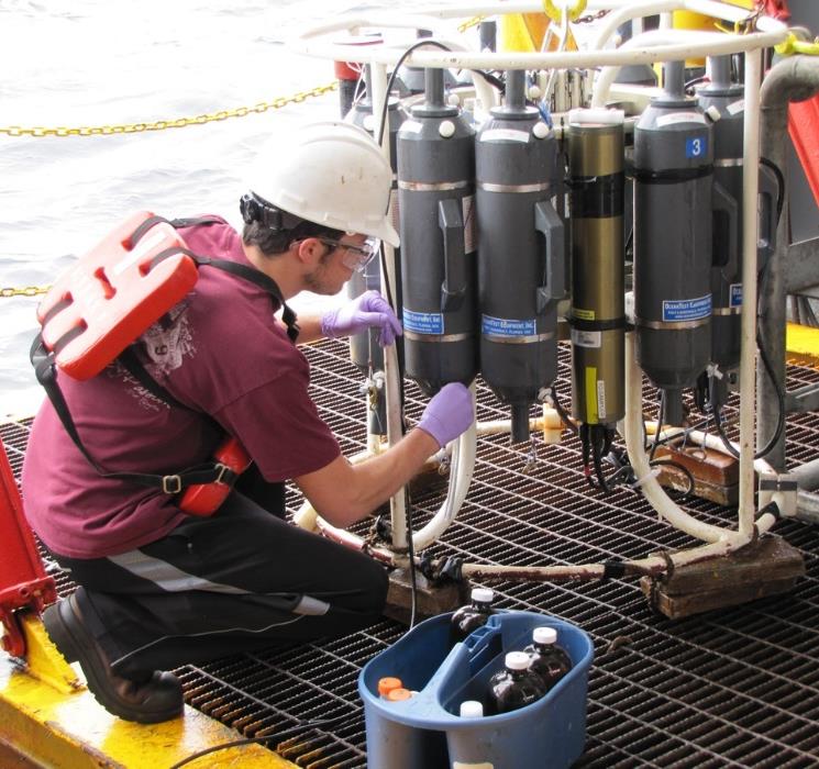
A custom designed and built clean shipboard laboratory area is used to process collected geochemistry cores in a hydrocarbon-free environment. Sections of the core are sampled based on a systematic sampling scheme dependent on core length. Geochemical, interstitial gas analysis and archive samples are collected from the bottom portion of each core and stored in a -20°C freezer until analysis in our Texas laboratory.
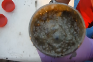
HEAVILY OIL STAINED PISTON CORE SAMPLE, OUT GASSING DUE TO PRESENCE OF GAS HYDRATES
CLICK BELOW & PLAY
Heat Flow Exploration
Heat flow measurements serve critical purposes in oil exploration and production. The measured background or equilibrium heat flow, and measured sediment thermal conductivity provide strict constraints to geochemical models that determine regional scale maturation of basins with respect to oil and gas. In addition, area-wide heat flow surveys provide significant geological information on fluid flow from faults, lineaments, and around structures. Heat flow measurements in conjunction with seismic and sea floor geochemical studies provide a mechanism to assess fault and structural seals and contribute to a better understanding of regional hydrodynamics and hydrocarbon occurrence.
 TDI-Brooks International has performed heat flow studies across the world. The map to the left shows the many locations we’ve collected heatflow measurements. TDI-Brooks International’s heat flow probe performs heat flow surveys in water depths up to 6000 m. In addition to measuring the sediment temperatures, the probe measures in situ thermal conductivity and water temperature profiles. The probe is capable of multiple measurements during a single 12-24 hour deployment. This one ton instrument is deployable from sea going vessels or platforms with a suitable winch and deployment system.
Sample Heat Flow Distribution
The heat flow in a region is due to heat moving upward from the mantle, together with thermal input from the radioactive decay of long-lived, naturally occurring isotopes in the earth’s crust. This conductive thermal regime is easily perturbed by the movement of fluids, which is the most effective form of heat transport. Thus, heat flow anomalies are indicative of recent or ongoing fluid flow in a sedimentary basin. Heat flow variations may also provide insight into basin stretching, sedimentation rates, and the presence of salt. Salt has a high thermal conductivity and thus enhances heat flow and perturbs maturation patterns and hydrodynamics around salt structures. In addition, the geotechnical stability of the ocean floor can be addressed as measured temperatures can determine the stability of gas hydrates in shallow sediments.
Download the Heat Flow Exploration flyer HERE
Laboratory Analysis
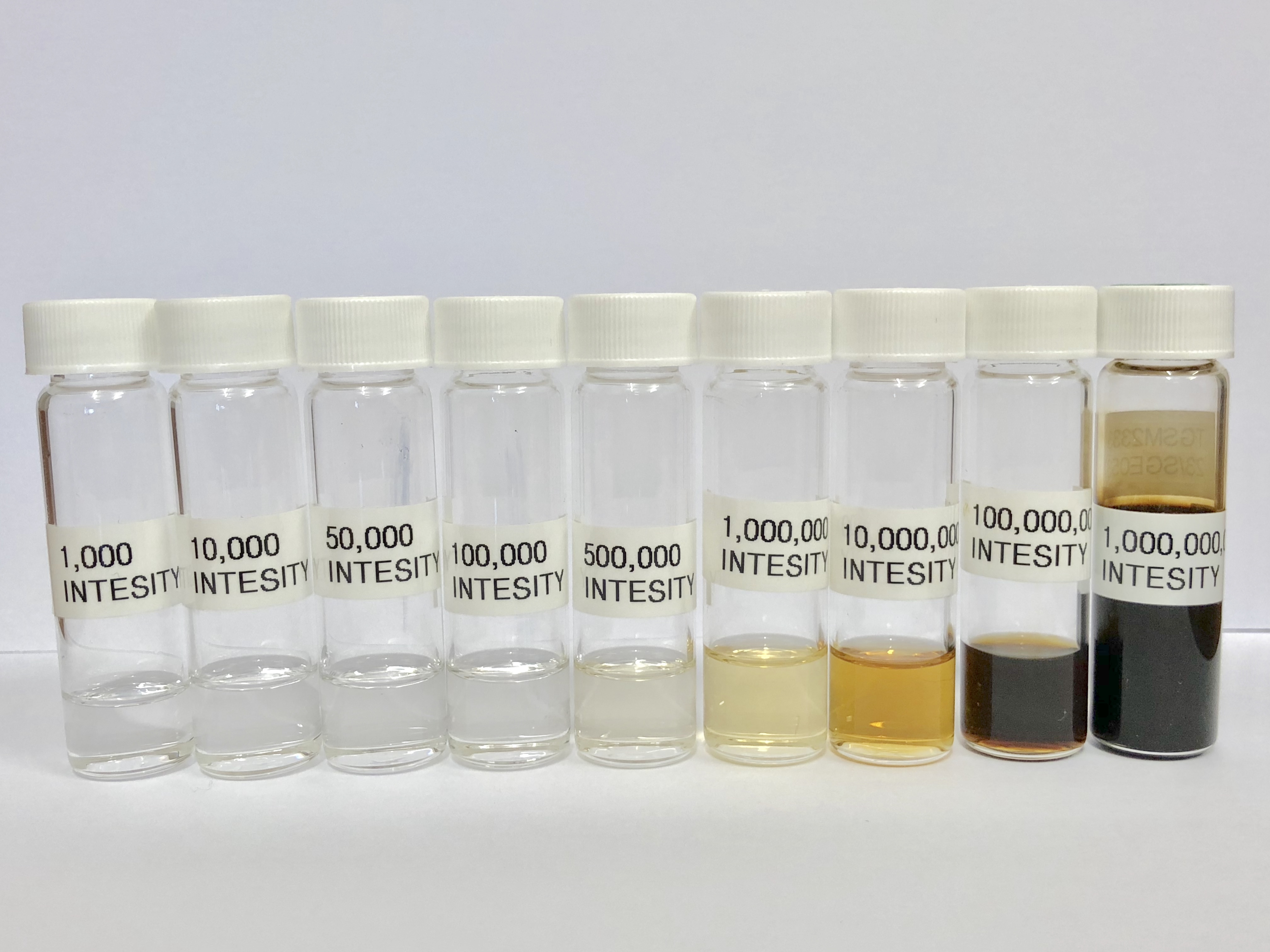
Total Scanning Fluorescence (TSF), C15+-hydrocarbon Gas Chromatographic analysis (C15+GC), and Interstitial Gas analysis (IG) are typically performed on each of the three core sections to evaluate them for the presence of migrated mature hydrocarbons. TSF provides information about petroleum-related aromatic hydrocarbons contained in sediment extracts. C15+GC analysis quantifies petroleum-related normal alkanes (n-C15 to n-C34), isoprenoids (pristane and phytane), and the unresolved complex mixture (UCM) generally associated with sediment extracts that contain oil.
The determination of interstitial light hydrocarbon gases (including methane, ethene, ethane, propene, propane, iso-butane, n-butane, neo-pentane, iso-pentane, and n-pentane) from canned sediment samples is useful because low molecular weight hydrocarbon gases are the most mobile phase of petroleum and, if present in the core section, are easily detected, quantified, and distinguished from local background.
Samples that contain elevated concentrations of migrated petroleum based on the TSF, C15+GC, and/or gas screening data can be further analyzed for saturate and aromatic biological markers and stable carbon isotopes. These more detailed analyses can usually confirm the presence of migrated petroleum and are often used to match hydrocarbons in the sediment extract with a specific produced oil and/or source rock.
Geochemical Interpretation
Abstract
Gas hydrates were recovered from eight sites on the Louisiana slope of the Gulf of Mexico. The gas hydrate discoveries ranged in water depths from 530 to 2400 m occurring as small to medium sized (0.5–50 mm) nodules, interspersed layers (1–10 mm thick) or as solid masses (> 150 mm thick). The hydrates have gas:fluid ratios as high as 170:1 at STP, C1/(C2 + C3) ratios ranging from 1.9 to > 1000 and δ13C ratios from −43 to −71‰. Thermogenic gas hydrates are associated with oil-stained cores containing up to 7% extractable oil exhibiting moderate to severe biodegradation. Biogenic gas hydrates are also associated with elevated bitumen levels (10–700 ppm). All gas hydrate associated cores contain high percentages (up to 65%) of authigenic, isotopically light carbonate. The hydrate-containing cores are associated with seismic “wipeout” zones indicative of gassy sediments. Collapsed structures, diapiric crests, or deep faults on the flanks of diapirs appear to be the sites of the shallow hydrates.
Abstract
Concentrations of the C1-C3 hydrocarbons and stable carbon isotope compositions of methane in recent sediments and seep gases of the Texas-Louisiana shelf-slope region were determined. These gases have been produced by both microbial and themocatalytic processes. Microbially-produced gases consist almost exclusively of methane, having C1/(C2+C3) hydrocarbon ratios greater than 1000 and δ13CPDB values of methane more negative than -60‰. Petroleum-related hydrocarbon gases generally have C1/(C2+C3) ratios smaller than 50 and isotopic ratios more positive than -50‰. A geochemical model based on these two parameters is used to show that natural gas compositions can be altered due to mixing of gases from the two sources as well as by microbial action and migration through sediments.
Light hydrocarbons in the upper few meters of Gulf of Mexico sediments are almost entirely of…
Bernard, B., 1978. Deep-Sea Research, Vol 26A, pp. 429 to 443.
Abstract
Interstitial methane profiles from six sediment cores taken on the slope and abyssal plain of the Gulf of Mexico can be explained by simple kinetic modeling. Methane is apparently produced at a constant rate and microbially consumed in the sulfate-reducing zone. Rates of production and consumption are estimated from best-fit solutions to a steady-state diagenetic equation. Production and consumption balance to form uniform concentrations of 5 to 10 µll-1 in the first few meters of slope and abyssal sediments. Effects of upward diffusion from large accumulations of methane in sulfate-free zones deeper than about 10m are not detectable.
Geochemical Laboratory Analysis
We take great pride in providing the highest quality trace-level geochemical analyses that go above and beyond the capabilities and scope of typical regulatory methods offered by other laboratories. Our methods are based on highly modified EPA methods that are performance-based and have been historically proven in numerous domestic and international programs over the past two decades. Our experienced geochemists review the data to ensure that they are scientifically sound and exceed our customer’s requirements and requests.
GEOCHEMICAL LABORATORY INFO HERE
Environmental baseline surveys
Environmental Baseline Surveys (EBS)
TDI-Brooks provides marine environmental baseline surveys (EBS) for coastal, nearshore and offshore projects for the oil & gas sector, offshore wind farm and other renewables programs, cables and pipelines. These services are provided on a global basis in GoM/Mexico, Northern South America (NSA) / Caribbean / Brazil and NW/W Africa regions.
Since inception of the EBS concept in the early 1970’s, TDI-Brooks’ scientists have been performing EBSs for clients in the most rigorous regulatory environments. Decades of experience in refning techniques, working with regulatory agencies, and developing a functional network of specialists/ associates provides our clients with an effective and defensible approach to resolving environmental impact issues in the marine environment.
We provide the following:
• Shallow and Deepwater Environmental Baseline Surveys
• Environmental and Social Impact Assessment Surveys
• Mapping of Protected Habitats
• Intertidal and Terrestrial Surveys
• Metocean Surveys
• Marine Weater Forecasting
• Oil Spill Continengency Plans
• Environmental Laboratory Analysis
Environmental Baseline Studies are often required in offshore prospects as a defense against potential litigation, to satisfy leasing stipulations, and as good faith measures in responsible environmental stewardship. When performed in conjunction with TDI-Brooks’ SGE surveys, we are able to leverage our experience, logistical support, and presence to provide cost effective EBSs conducted under the stringent HSE standards that industry demands, thereby providing our client with timely solutions to environmental concerns backed with the highest scientific and technical credibility.
Our scientists have held key roles in the most high profile, prestigious Environmental Impact Assessment projects both in the US and internationally. Our client history includes USEPA, BOEM (formerly Minerals Management Service), National Oceanic and Atmospheric Administration, Office of Naval Research, and US Fish and Wildlife Service.
Download the Environmental Baseline Surveys flyer HERE
Contact us with any questions: info@tdi-bi.com
metocean surveys
TDI-Brooks provides Metocean services to the oil and gas industry, ports and harbor authorities, renewable energy companies, government agencies, and engineering firms worldwide.
TDI-Brooks offers complete investigations for oil and gas exploration, dredging operations and offshore constructions including benthic and water sampling, long-term real-time weather, sea state and pack ice monitoring through bespoke web applications, tide and current measurements as well as underwater noise monitoring.
Before undertaking any development works within the marine environment it is important to understand the mechanics of the sometimes harsh and challenging surroundings within the proposed project area. This means developing and understanding the impacts and effects of wind, waves, currents and tidal patterns on both the existing infrastructure and any future development
We provide comprehensive feasibility and desktop studies for the initial stage of project planning where often a comprehensive pre-analysis of the existing area will lead to time and cost savings during the life cycle of the project.
TDI-Brooks uses a wide range of Metocean equipment from shallow water to deep oceans including tide gauges, wave and current meters, in-situ data loggers and meteorological stations in order to gather detailed information on the meteorological and oceanographic conditions at the survey area.
- Full water column oceanographic data acquisition, including current velocity and direction, wave spectra, tides, conductivity, and temperature (shallow waters to ultra deep waters)
- Meteorological stations, including wind, temperature, cloud height, and visibility
Design, installation, and maintenance of tide stations for ports, exploration, and survey programs - Integration of instrumentation and sensors through buoy-based systems or fiber networks utilizing sophisticated data processing, web display, storage, and dissemination software
- Consultancy, design and installation of acoustic monitoring systems to support offshore operations including site investigations and environmental impact assessments.
- Long-term measurements to provide information concerning acoustics and the potential effects of marine operations on the environment.
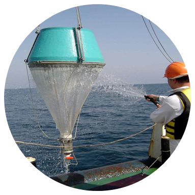
TDI-Brooks provides benthic sampling services in coastal and deep water environments using box cores and grab samplers. Benthic sampling is carried out to establish an inventory of the flora and fauna.
Marine Weather Forecasting
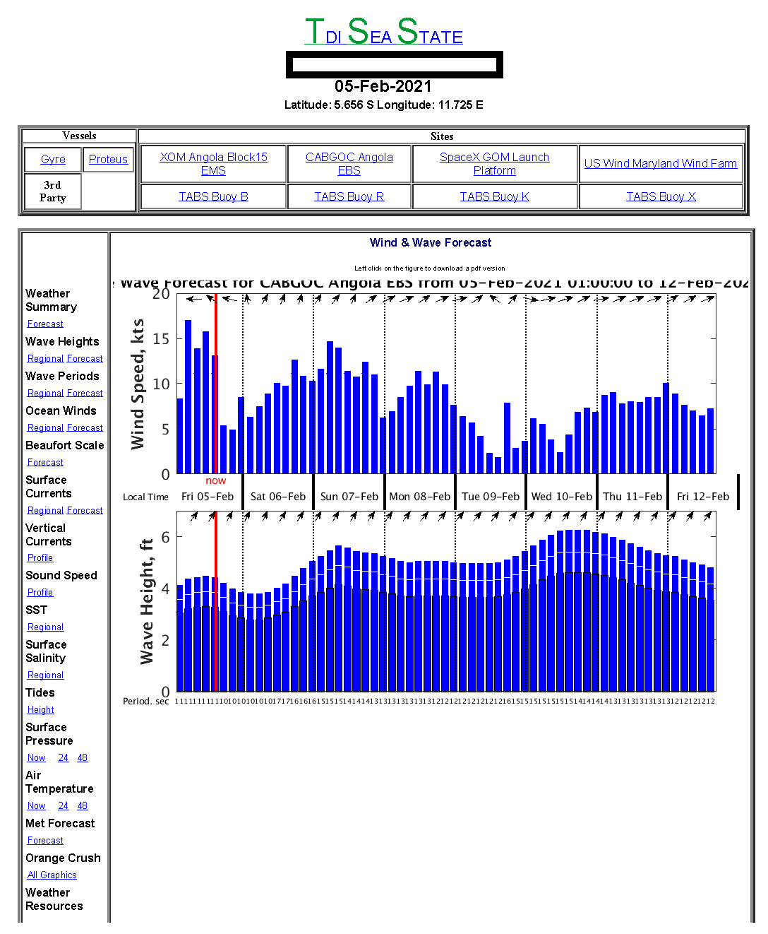
TDI-Brooks offers customized marine weather forecast services to meet the requirements of our clients operating in the offshore environment. Marine forecasting helps manage the risks and planning of offshore operations. All marine operators can safely and and accurately plan thier operations in an effort to improve the safety and efficiency of the offshore operations. Our proven method has been used internally for over 250 projects with great success since 2014.
We use the most up to date technologies to provide highly accurate forecasts, ensuring operations are planned, both safely and efficiently.
We offer advanced knowledge of the wind and wave conditions which leads to safer, more efficient offshore operations.
Weather forecasts including meteorological data provides a general synopsis and any warnings (gale, hurricane, etc.).
Offshore Weather Services Offered:
- weather forecasts for the oceans
- day-to-day planning
- site specific forecasts to support daily operations
- route forecasts
- onsite weather forecasts
- weather downtime
- hurricane and lighning warnings
- a summary of the wind
- seas
- wave and swell forecast
- existing weather and forecast weather
- and an outlook for the appropriate period for wind, sea and swell
The Effect of Bottom Water Temperature
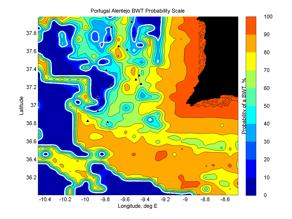
Figure 10: Probability of a BWT transient offshore of Portugal. The heat flow sites are denoted with a black triangle.
The temperature of the ocean water overlying the bottom, known as bottom water temperature (BWT), plays an important role in obtaining a reliable heat flow estimate. Understanding how changes to the BWT can affect a computed heat flow value is very important. If the BWT cools or heats suddenly, then this sends a temperature anomaly propagating by conduction downward into the sediments. Sometimes such changes in the BWT are responsible for large, non-linear temperature variations over the length of the 5-m probe, particularly at shallow water sites. TDI-Brooks recommends that heat flow be conducted in depths greater than 600-800m because of the high risk of a BWT variation in shallow water. Normally in the deep ocean the BWT is fairly stable with depth, and varies only slightly in time. This is conducive to highly accurate and precise heat flow measurements. But BWTs may not be stable at any depth depending on the oceanographic factors.
Bottom water temperature transients have typically been identified after the fact, by recognizing a deviation from linearity in the Bullard plot and then explaining the deviation as a probable transient in the temperature of the overlying water. But it is possible to examine the bottom water temperature output of a real-time ocean model and pro-actively identify potential sites where transients could be expected to be a problem. TDI-Brooks has the capability to classify whether a potential heat flow site may be subject to a transient in the bottom water temperature. The method will correctly classify a heat flow site as stable or unstable with an accuracy exceeding 90%. For example, Figure 1 shows the computed probability of a BWT transient offshore of southern Portugal. This region is influenced by the warm and highly saline Mediterranean Outflow Water flowing out of the Gibraltar Strait and to the northwest over the Portuguese margin. The Outflow occurs between 500 and 1400m and affects the BWT of sites typically considered to be deep. Table 1 provides the specific details found by our method. The column labeled Bullard Plot shows if a transient was detected in the Bullard Plot. The column labeled Computed BWT Probability shows the computed probability of a transient. A probability greater than 30% is highly indicative of a transient. None of the site depths were less than 1100 m, yet all but two were affected by a transient. The method correctly identified eleven of the twelve sites, or 91%.
For more information, or a copy of the technical note (click here to download) further describing the method, please contact Dr. Les Bender at +1 979.693.3446 or lesbender@tdi-bi.com.
|
Station ID |
Depth, m |
Bullard Plot |
Computed BWT Probabiity, % |
|
HF-PPF-c |
1452 |
BWT Transient |
78.31 |
|
HF-PPF-e |
1121 |
BWT Transient |
67.81 |
|
HF-PPF-f |
2170 |
BWT Transient |
38.33 |
|
HF-PPF-g |
2751 |
BWT Transient |
72.57 |
|
HF-PPF-h |
2475 |
BWT Transient |
55.93 |
|
HF-PPF-i |
3304 |
Equilibrium heat flow – no transient |
17.13 |
|
HF-PPF-j |
3429 |
Equilibrium heat flow – no transient |
33.60 |
|
HF-PPF-k |
1247 |
BWT Transient |
78.63 |
|
HF-PPF-l |
1197 |
BWT Transient |
63.47 |
|
HF-PPF-n |
1423 |
BWT Transient |
50.13 |
|
HF-PPF-o |
1332 |
BWT Transient |
47.07 |
|
HF-PPF-p |
2140 |
BWT Transient |
41.51 |
Environmental Laboratory
Our company has over 20 years of experience and has been the choice laboratory for programs such as NOAA’s Status and Trends Mussel Watch (1999-currently), United States Fish and Wildlife Analytical Control Facility (2002-currently), oil spill response as with Mississippi Canyon 252 (Deepwater Horizon) Natural Resource Damage Assessment (2010-currently).
Our company has been ISO 9001 accredited since 2011 and is currently in the process of obtaining ISO 17025:2017 accreditation.
ENVIRONMENTAL LABORATORY INFO HERE
geophysical survey services
MARINE gEOPHYSICAL Surveys
TDI-Brooks provides full arrays of hull-mounted and towed sensor acquisition systems to perform hydrographic and marine geophysical surveys around the world safely, effectively, and economically. TDI-Brooks has the global experience, knowledge and resources needed for any marine site survey investigation.
TDI-Brooks employs an experienced team which includes hydrographers, geophysicists, geologists, oceanographers, mariners, cartographers, and GIS and CADD specialists to produce surveys and deliverables of the highest quality.
Areas of Expertise include the following:
| 2DHR Seismic multi-channel surveys | Cable Route Surveys |
| Marine archeological & hazard surveys | Burial assessments |
| Hydrographic mapping | UXO surveys |
| Tow route clearances | Bureau of Ocean Energy Management (BOEM) surveys |
| Platform and pipeline damage assessments and inspection | Academic research |
| Pipeline route surveys |
Download the Marine Geophysical flyer HERE
 |
Marine geophysical surveys are critical to any site investigation and/or seabed mapping project. Marine geophysical survey is the science of measurement and description of features which affect maritime navigation, marine construction, dredging, offshore oil exploration/offshore oil drilling and related activities. For hydrographic surveys a strong emphasis is placed on soundings, shorelines, tides, currents, seabed and submerged obstructions that relate to the previously mentioned activities.
Each TDI-Brooks vessel uses an array of specialized tools to conduct marine geophysical surveys. Along with TDI-Brooks pre-mobilized vessels, we offer portable tool kits which can be shipped to any vessel of opportunity.
TDI-Brooks has conducted a number of high-profile marine geophysical surveys (hazard, hydrographic, shallow 2-D seismic, etc). A marine geophysical survey involves a number of data requirements including water depths, seabed topography, seabed and sub-seabed obstructions, seabed soils, shallow geology and ground conditions and identification of any man-made and naturally occurring hazards that may adversely impact the objective of the site investigation (geohazards).
The basic survey package consists of:
- Side Scan Sonar
- Conducting cable winch and slip ring
- Marine Magnetometer
- Sub-Bottom Profiler
- USBL system
- DPGS System and navigation package
- Single-Beam Echo Sounder
- CTD Profiler
- MRU
- Multi-Beam Echo Sounder
- 2-D Seismic System
Contact us with any questions: info@tdi-bi.com
renewables - offshore wind
Download the Offshore Wind flyer HERE
TDI-Brooks acquires, processes and interprets geological, geophysical and geotechnical data to assist in assessing the suitability of offshore sites for wind farms and their infrastructure.
TDI-Brooks helps plan the construction of commercial scale wind farms requiring the knowledge the geologic makeup and condition of the seafloor. Each of these items are critical to plan the type of foundation for the turbines, the magnitude of ground disturbance and geoengineering that will be required to set that foundation, the presence of hazards to the construction/maintenance activities and the specific layout of the field. We have extensive experience, providing detailed analyses of the seabed and accurate assessments of subsurface conditions for offshore windfarm sites.
TDI-Brooks for the past 25 years has been a part of highly-successful oil & gas programs across the globe in the Oil & Gas sector. The offshore wind industry is loearnhing from the oil & gas industry when it comes to successfully co-existing with other maritime industries. Offshore wind is being seen as a major contributor post-COVID economical recovery by governments around the world.

TDI-Brooks has deployed 2 of their research vessels to the East Coast of the US to serve the offshore wind farm market. Both multi-use oceanographic research vessels are equipped to acquire geophysical surveys for offshore hazard/site clearance assessments, pipeline/cable routing, seafloor mapping, port and channel conditions, fisheries habitat mapping and burial assessment studies. TDI-Brooks will engage in the seabed geophysicaand geotechical surveys to better understand the geological issues that may exist with project development to ensure safe and long-term operations and performance of the facilities.
- Norbit Winghead Multibeam (dual head) with QPS QINSy 9
- Edgetech 4205 SSS with Discover and QPS QINSy 9
- Geometrics G882 configured in TVG with MagLog and QPS QINSy 9
- INNOMAR SES2000 SBP with SEISWIN
- Applanix POS MV with Norbit MBES interface
- Sonardyne Mini-Ranger 2
- Xylem Castaway CTD
- Single-Channel boomer with SonarWiz
The TDI-Brooks fleet is operated within a robust Safety Management System and all vessels are regularly vetted by client marine assurance groups and a part of the OCIMF Offshore Vessel Inspection Database (OVID).
TDI-Brooks Solutions for Offshore Wind
Prior to the construction of an offshore wind facility, site characterization surveys are required to evaluate the impact of seafloor and sub-seafloor (sub-bottom) conditions on the construction, operation and structural integrity of the proposed area.
When integrated with geotechnical results from core samples and data from bathymetric and other surface condition surveys, the data collected provides a key insight that ultimately helps to determine the suitability of proposed offshore installations, helping to create and sustain the future of renewable offshore energy.
- Geophysical and hydrographic surveys to ascertain seabed bathymetry, morphology, classification, marine habitats and sub-seabed layers.
- Preliminary geotechnical surveys and engineering services to characterize and classify sub-seabed layers • Environmental sampling and testing
- Cable route selection and survey
- Laboratory testing including soil dynamics testing on specimens obtained during field work
- Wind Farm noise impact assessment – baseline noise measurements
- Local and regional metocean measurements to support operational planning and engineering

Contact Us
TDI-Brooks
14391 S Dowling RD
College Station, TX 77845
Email: info@tdi-bi.com
Phone: +1 (979) 693-3446


Quick Links

Sitemap
- Home
- About
- Field Acquisition Services
- Vessels & Charters
- Analytical Services
- Available Piston Core and Heatflow Program Data
- Locate Us
- Contact Us
- Resources & Resumes
- Careers